How to Terminate Output Wiring Connection to Extra Output Points on XP-GLS5000 Controller and to Configure the Outputs

Problem (Issue) Statement:

How to terminate output wiring connection to extra output points on XP-GLS5000 controller and to configure the outputs

Description:

A guide to terminate output wiring connection to extra output points on XP-GLS5000 controller and to configure the outputs.

Related Software:

  • xPortalNet HS v1.5.0.21 and above

Related Hardware:

  • XP-GLS5000 v1.16 above

System Application:

  • Door Access System
  • Alarm Monitoring System

Symptom and Finding:

NA

Cause:

For first time guide to terminate output wiring connection to extra output points on XP-GLS5000 controller and to configure the outputs.

Solution:

Summary:

.

Note

XP-GLS5000 controller can be configured to operate in two different modes which allow users to configure the additional output for alarm monitoring purposes:

  • Door access with alarm monitoring - User can use output terminals Relay 7 and Relay 8. Output terminals Relay 1 to Relay 5 are assigned for door access monitoring.
  • Alarm only mode - User can use all output terminals from Relay 1 to Relay 8

Different operation modes can affect the output points available for configuration and termination

.

.


Step by step Guide:

  • To terminate wiring for output and to set output jumper settings:

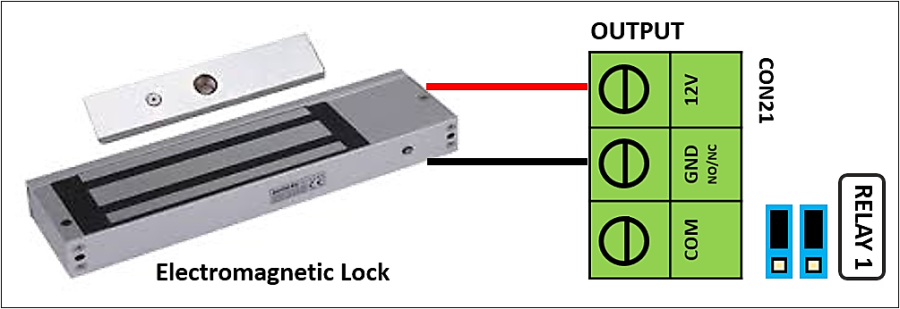
Step 1: Refer to wiring diagram as shown below for wet contract output with NC (Normally Closed) contact type.
Wiring Diagram for Wet Contact Output (Electromagnetic Lock) with Normally Closed Contact Type
Figure 1: Wiring Diagram for Wet Contact Output (Electromagnetic Lock) with Normally Closed Contact Type


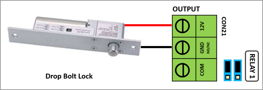
Or


Wiring Diagram for Wet Contact Output (Drop Bolt Lock) with Normally Closed Contact Type
Figure 2: Wiring Diagram for Wet Contact Output (Drop Bolt Lock) with Normally Closed Contact Type 


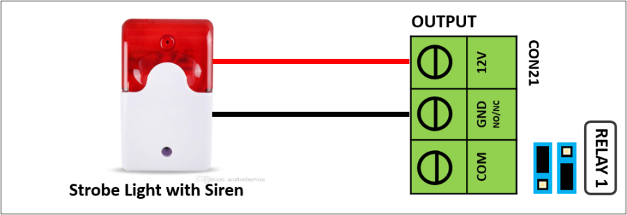
Step 2: Refer to wiring diagram as shown below for wet contact output with NO (Normally Opened) contact type.
Wiring Diagram for Wet Contact Output (Strobe Light with Siren) with Normally Opened Contact Type
Figure 3: Wiring Diagram for Wet Contact Output (Strobe Light with Siren) with Normally Opened Contact Type 


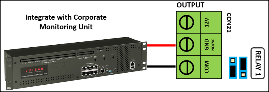
Step 3: Refer to wiring diagram as shown below for dry contact output with NC (Normally Closed) contact type.
Wiring Diagram for Dry Contact Output (Integration with PA System) with Normally Closed Contact Type
Figure 4: Wiring Diagram for Dry Contact Output (Integration with PA System) with Normally Closed Contact Type 


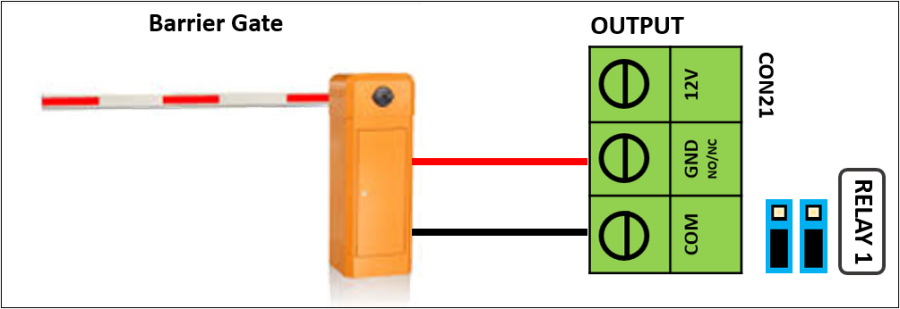
Step 4: Refer to wiring diagram as shown below for dry contact output with NO (Normally Opened) contact type.
Wiring Diagram for Dry Contact Output (Traffic Barrier Gate) with Normally Opened Contact Type
Figure 5: Wiring Diagram for Dry Contact Output (Traffic Barrier Gate) with Normally Opened Contact Type 
.

.

  • To configure Alarm Controller Setup in xPortalNet Server:

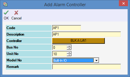
Step 1: Go to Server Admin > System Device Setup > Alarm Controller > Add. The Add Alarm Controller window will be shown as below:
Alarm Controller Window
Figure 6: Alarm Controller Window


Note

To use the internal I/O configuration on XP-GLS5000 controller, the Unit No field MUST be configured to 10.

.

.
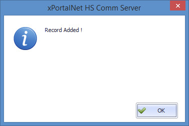
Step 2: The following message window will be prompted to show Record is Added. Click OK to continue.
Record Added Window
Figure 7: Record Added Window
.

.

  • To configure Output Point Setup in xPortalNet Server:

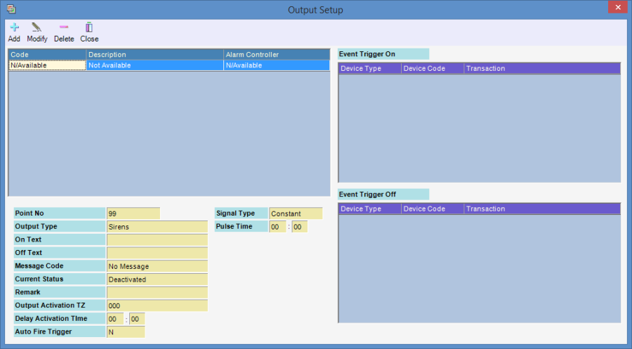
Step 1: Go to Server Admin > System Device Setup > Output Point. The Output Setup window will be shown as below.
Output Setup Window
Figure 8: Output Setup Window


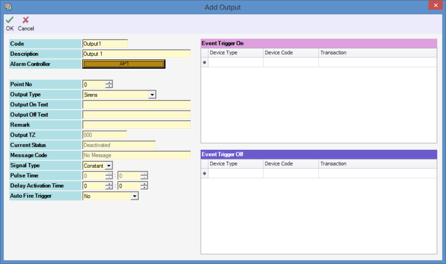
Step 2: Click Add to add a new output setup. The Add Output window will be shown as below.
Add Output Window
Figure 9: Add Output Window


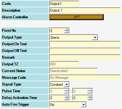
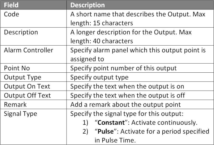
Step 3: Fill in the respective fields and click OK to save the changes.
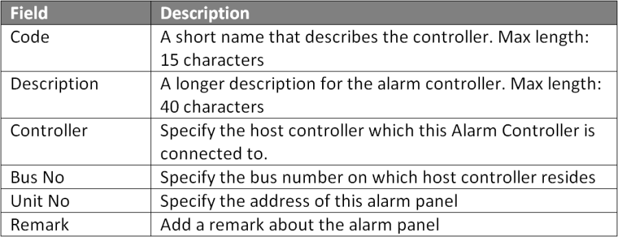
Output Table Fields
Figure 10: Output Table Fields


Note

  • For Door Access with Alarm Mode - Users can only use Output Relays 6 to 8 (point no start from 5 - 7). Relays 1 to 5 are allocated for Door Access.
  • For Alarm Mode only - Users can use all relays from 1 to 8 (point no from 0 - 7)

.

.
Step 4: The following message window will be prompted to show that Record is Added. Click OK to continue.
Record Added Window
Figure 11: Record Added Window


Step 5: Users can proceed to configure built- in input points on the controller and create an Instruction Control configuration to specify the relationship between the Input & Output points.

Common Issue:

  • Most of the times, technical site support confused the DIP switch settings for the different operation modes.

Date Documentation:

27/5/2019 (Rev 1.1)

PROOF-READ

.

Related Articles.

Containing the label "xp-gls5000"

Filter by label

There are no items with the selected labels at this time.

.


.

© MicroEngine Technology Sdn Bhd (535550-U). All rights reserved.