How to Terminate Sensor Wiring Connection to Extra Inputs on XP-GLS5000 Controller and to Configure the Inputs for Alarm Monitoring Purposes
Problem (Issue) Statement: | How to terminate sensor wiring connection to extra inputs on XP-GLS5000 controller and to configure the inputs for alarm monitoring purposes. |
Description: | A guide to terminate sensor wiring connection to extra inputs on XP-GLS5000 controller and to configure the inputs for alarm monitoring purposes. |
Related Software: |
|
Related Hardware: |
|
System Application: |
|
Symptom and Finding: | NA |
Cause: | For first time connection and terminate wiring connection for extra inputs on XP-GLS5000 board. |
Solution: | Summary:
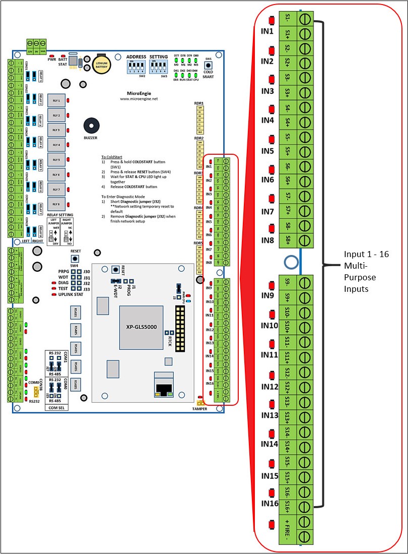
Note XP-GLS5000 controller can be configured to operate in two different modes which allow users to configure the additional input for alarm monitoring purposes:
Different operation modes can affect the alarm input points available for configuration and termination. ..
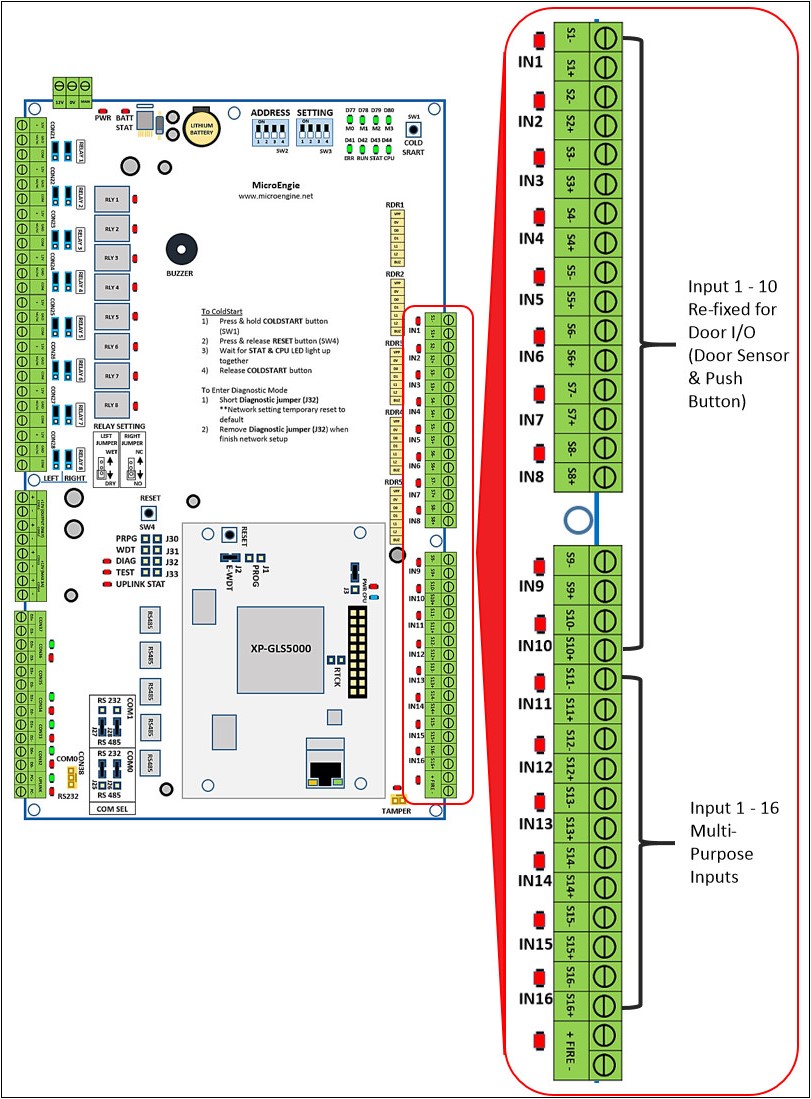
Step 1: Please refer to the wiring diagram below for alarm sensor input termination in door access with alarm monitoring mode. Users can use input terminal IN11 to IN16. Input terminal IN1 to IN10 are assigned for Door Access.
Note
. .
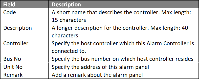
Step 1: Go to Server Admin > System Device Setup > Alarm Controller > Add. The Add Alarm Controller window will be shown as below:
Note For internal I/O configuration on XP-GLS5000 controller, the Unit No field MUST be configured to "10". . . .
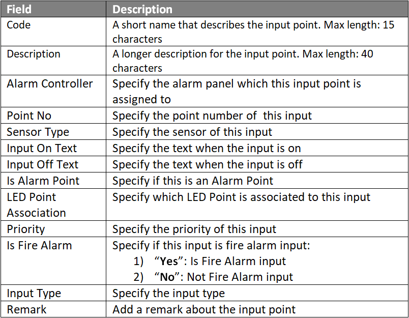
Step 1: Go to Server Admin > System Device Setup > Input Point. The Input Setup window will be shown as below.
. Step 4: Users can proceed to configure built- in controller of Output Point and create an Instruction Controller to configure the relationship between the Inputs & Outputs points.Knowledge Base Link
|
Date Documentation: | 15/8/2018 (Rev 1.0) |


PROOF-READ
.
.
.
© MicroEngine Technology Sdn Bhd (535550-U). All rights reserved.