How to Terminate Output Wiring Connection to Extra Output Points on XP-GLS5000 Controller and to Configure the Outputs

How to Terminate Output Wiring Connection to Extra Output Points on XP-GLS5000 Controller and to Configure the Outputs

Problem (Issue) Statement:

How to terminate output wiring connection to extra output points on XP-GLS5000 controller and to configure the outputs

Description:

A guide to terminate output wiring connection to extra output points on XP-GLS5000 controller and to configure the outputs.

Related Software:

  • xPortalNet HS v1.5.0.21 and above

Related Hardware:

  • XP-GLS5000 v1.16 above

System Application:

  • Door Access System

  • Alarm Monitoring System

Symptom and Finding:

NA

Cause:

For first time guide to terminate output wiring connection to extra output points on XP-GLS5000 controller and to configure the outputs.

Solution:

Summary:

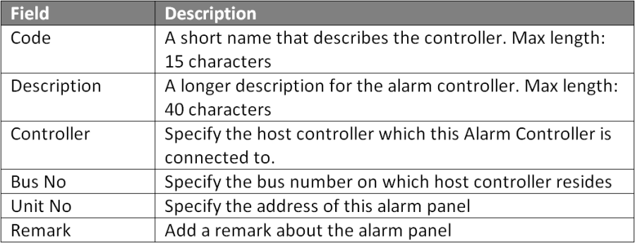
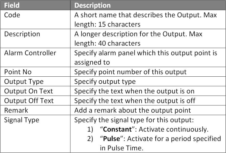
.

Note

XP-GLS5000 controller can be configured to operate in two different modes which allow users to configure the additional output for alarm monitoring purposes:

  • Door access with alarm monitoring - User can use output terminals Relay 7 and Relay 8. Output terminals Relay 1 to Relay 5 are assigned for door access monitoring.

  • Alarm only mode - User can use all output terminals from Relay 1 to Relay 8

Different operation modes can affect the output points available for configuration and termination

.

.


Step by step Guide:

  • To terminate wiring for output and to set output jumper settings:

Step 1: Refer to wiring diagram as shown below for wet contract output with NC (Normally Closed) contact type.


Figure 1: Wiring Diagram for Wet Contact Output (Electromagnetic Lock) with Normally Closed Contact Type


Or


Figure 2: Wiring Diagram for Wet Contact Output (Drop Bolt Lock) with Normally Closed Contact Type 


Step 2: Refer to wiring diagram as shown below for wet contact output with NO (Normally Opened) contact type.


Figure 3: Wiring Diagram for Wet Contact Output (Strobe Light with Siren) with Normally Opened Contact Type 


Step 3: Refer to wiring diagram as shown below for dry contact output with NC (Normally Closed) contact type.


Figure 4: Wiring Diagram for Dry Contact Output (Integration with PA System) with Normally Closed Contact Type 


Step 4: Refer to wiring diagram as shown below for dry contact output with NO (Normally Opened) contact type.


Figure 5: Wiring Diagram for Dry Contact Output (Traffic Barrier Gate) with Normally Opened Contact Type 
.

.

  • To configure Alarm Controller Setup in xPortalNet Server:

Step 1: Go to Server Admin > System Device Setup > Alarm Controller > Add. The Add Alarm Controller window will be shown as below:


Figure 6: Alarm Controller Window


Note

To use the internal I/O configuration on XP-GLS5000 controller, the Unit No field MUST be configured to 10.

.

.
Step 2: The following message window will be prompted to show Record is Added. Click OK to continue.


Figure 7: Record Added Window
.

.

  • To configure Output Point Setup in xPortalNet Server:

Step 1: Go to Server Admin > System Device Setup > Output Point. The Output Setup window will be shown as below.


Figure 8: Output Setup Window


Step 2: Click Add to add a new output setup. The Add Output window will be shown as below.


Figure 9: Add Output Window


Step 3: Fill in the respective fields and click OK to save the changes.


Figure 10: Output Table Fields


Note

  • For Door Access with Alarm Mode - Users can only use Output Relays 6 to 8 (point no start from 5 - 7). Relays 1 to 5 are allocated for Door Access.

  • For Alarm Mode only - Users can use all relays from 1 to 8 (point no from 0 - 7)

.

.
Step 4: The following message window will be prompted to show that Record is Added. Click OK to continue.


Figure 11: Record Added Window


Step 5: Users can proceed to configure built- in input points on the controller and create an Instruction Control configuration to specify the relationship between the Input & Output points.

Common Issue:

  • Most of the times, technical site support confused the DIP switch settings for the different operation modes.

Date Documentation:

27/5/2019 (Rev 1.1)

© MicroEngine Technology Sdn Bhd (535550-U). All rights reserved.