How to Connect XP-SNET controller to Door Accessories and Extension Boards
| Problem (Issue) Statement: | How to connect XP-SNET controller to door accessories and extension boards |
| Description: | XP-SNET is MicroEngine's multi-door, multi application controller. It can be support up to 10 doors for normal door access application, and can also support other modes such as Alarm Monitoring Mode and Lift Masking Mode. |
| Related Software: | NIL |
| Related Hardware: |
|
| System Application: | NIL |
| Symptom and Finding: | NIL |
| Cause: | For first time guide on how to connect XP-SNET controller to door accessories and extension boards. |
| Solution: | Warning! The XP-SNET controller will not send fire alarm signal over to the connected XP-SNET-E32R and/or XP-SNET-E248 extension boards if the configuration settings for the XP-SNET controller is not completed.Complete the configuration settings for XP-SNET controller in order for XP-SNET-E32R and/or XP-SNET-E248 to respond accordingly to fire alarm signals.. . Summary:
. Step-by-step Guide:
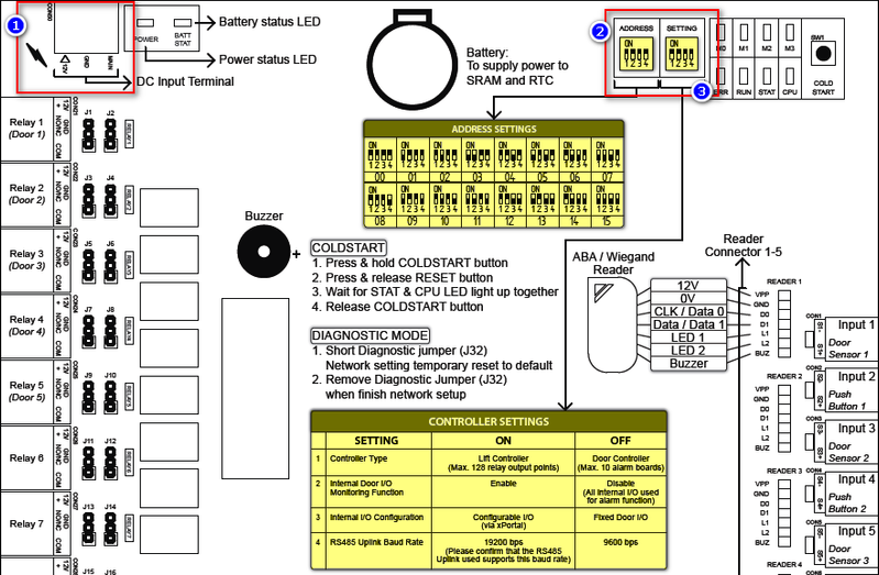
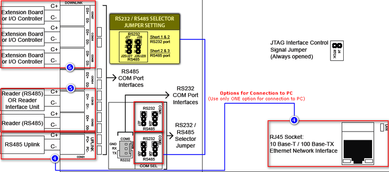
Please refer to the following wiring diagram for the connections between the XP-SNET controller to door accessories and extension boards.
Step 1: Connect the +12V and GND terminals to the power supply unit (12VDC). Then, short the Main terminal to 12VDC as a main power monitor. Step 2: At the ADDRESS DIP Switch, assign a unique address number to this XP-SNET controller. Note that no two controllers in the network can have the same address number. Refer to the attached ADDRESS SETTINGS table for the correct configuration for different address numbers. Step 3: At the SETTING DIP Switch, configure the relevant controllers setting according to the CONTROLLER SETTINGS table. Step 4: For MCI connection to PC (using RS485 / RS232), connect the C+ and C- connector from the MCI to the Uplink terminal. Step 5: Connect the readers' RS485 data line to CON32 or CON33. Users can also connect the Reader Interface Module unit's RS485 data line to CON33. Step 6: Users can connect RS485 data line from extension boards to CON34, CON35, or CON36 if the application is using extension boards. |
| Common Issues: | NIL |
| Porting Date: | 29/3/2019 |
PROOF-READ
.
.
.
© MicroEngine Technology Sdn Bhd (535550-U). All rights reserved.

