Why did the Legacy XP-GT or XP-GTR Controller not Release the EM Lock Although Controller Already Showed Valid Entry Access Message
| Problem (Issue) Statement: | Why did the legacy XP-GT or XP-GTR controller not release the EM lock although controller already showed Valid Entry Access message |
| Description: | When card users flashed the valid access card at the legacy XP-GT or XP-GTR controller, the EM lock for the door was not released, even though the controller's LCD screen already showed the Valid Entry Access message. |
| Related Software: | NIL |
| Related Hardware: |
|
| System Application: | NIL |
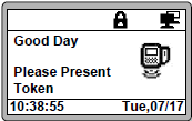
| Symptom and Finding: | The EM lock for the door was not released, although the controller already responded to the flashed valid access card by displaying the Valid Entry Access message. The controller's LCD screen does not show the downlink icon of , as shown in the LCD screenshot as shown below: |
| Cause: |
|
| Solution: | Summary: . . Step-by-step Guide:
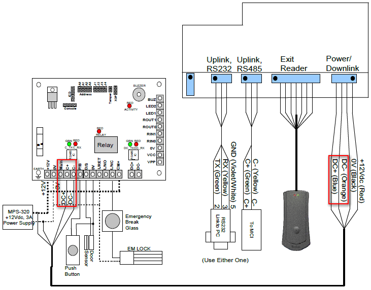
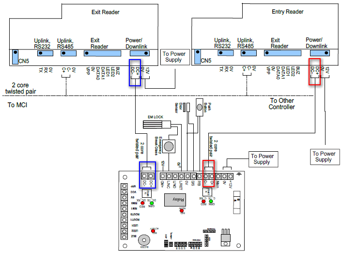
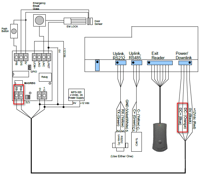
1 Unit XP-GT Controller to MAS-RBT Relay Board: Step 1: Please follow the wiring diagram as shown below: . 2 Units XP-GT Controller to MAS-RBT Relay Board: Step 1: Please follow the wiring diagram as shown below: . 1 Unit XP-GTR Controller to MAS-RBU Relay Board: Step 1: Please follow the wiring diagram as shown below: . .
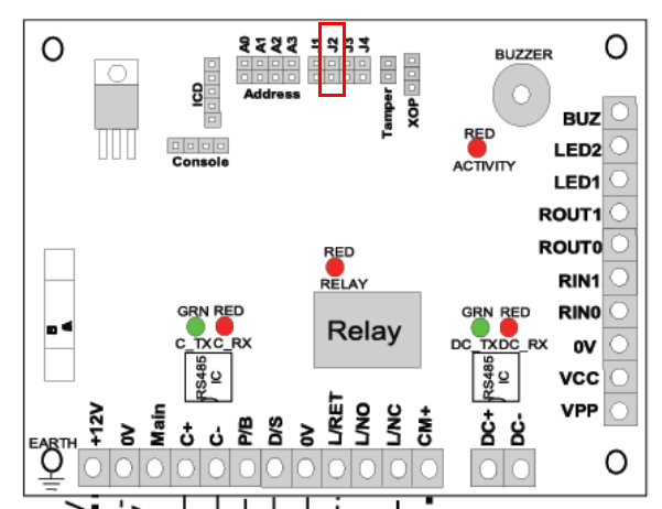
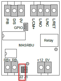
For XP-GT Controller to MAS-RBT Relay Board: Step 1: Ensure that the jumper J2 at MAS-RBT relay board is opened. . For XP-GTR Controller to MAS-RBU Relay Board: Step 1: Ensure that the jumper J2 at MAS-RBU relay board is shorted. . .
Step 1: If the problem still persists, users are adviced to troubleshoot to ensure that the controller and the relay board units are functioning well.
. Step 2: If any of the units are faulty, kindly send them to our Service Center for repairs. |
| Common Issues: | NIL |
| Porting Date: | 31/10/2019 |
PROOF-READ
.
.
.
© MicroEngine Technology Sdn Bhd (535550-U). All rights reserved.
