How to Connect XP-GLS5000 Controller with XP-SNET-E248 or XP-SNET-E32R Extension Board for Alarm Monitoring System Application

Problem (Issue) Statement:

How to connect XP-GLS5000 controller with XP-SNET-E248 or XP-SNET-E32R Extension Board for Alarm Monitoring System Application
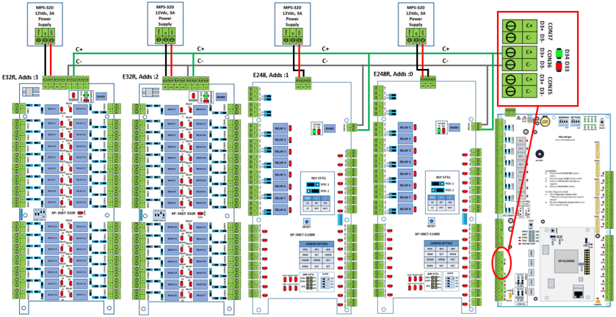
Description:

A guide to connect XP-GLS5000 controller to XP-SNET-E248 / XP-SNET-E32R extension board for Alarm Monitoring System application.

Related Software:

  • xPortalNet HS v1.8.0.7 and above

Related Hardware:

  • XP-GLS5000 v1.16 and above
  • XP-SNET-E32R
  • XP-SNET-E248

System Application:

  • Alarm Monitoring System

Symptom and Finding:

NA

Cause:

For first time guide to connect XP-GLS5000 controller to XP-SNET-E248 / XP-SNET-E32R extension board for Alarm Monitoring System application.

Solution:


Summary:


Step-by-step Guide:

  • To connect XP-SNET-E248 / XP-SNET-E32R extension board to XP-GLS5000 controller:

Step 1: Please follow the wiring diagram as shown below:

Figure 1: Wiring diagram between XP-SNET-E248 / XP-SNET-E32R extension boards to XP-GLS5000 controller


Note

  • Users are required to assign a unique address number to each extension board within the same connection bus.
  • One (1) unit of XP-GLS5000 controller is able to support up to a maximum of 128 points of input and 128 points of relay output

.

.

Step 2: Users can now proceed to configure the address settings for the extension boards to facilitate communication in the network.
.

.

  • To configure DIP switches for address setting on XP-SNET-E248 / XP-SNET-E32R extension board:

Step 1: For XP-SNET-E248 extension board.

Knowledge Base Link

Users may refer to How to Configure Address Unit no on XP-SNET-E248 Extension Board for the complete procedures to configure address settings for XP-SNET-E248.

.

.
Step 2: For XP-SNET-E32R extension board.

Users may refer to How to Configure Address Unit No on XP-SNET-E32R Extension Board for the complete procedures to configure address settings for XP-SNET-E32R.

.

.

  • To observe the XP-SNET and XP-SNET-E248 / XP-SNET-E32R response after configuring the address of XP-SNET-E32R:

Step 1: Please ensure that door setting has sent to XP-GLS5000 controller.

Users may refer to How to Send or Download Data to the Controller for the complete procedures to send door settings to the controller.

.

.
Step 2: Next, on the XP-GLS5000 controller, ensure that both D33 & D34 LEDs in the "Downlink" section (lower left section of XP-GLS5000 controller) is blinking to indicate that the XP-GLS5000 controller has successfully established communication with the XP-SNET-E248 / XP-SNET-E32R extension board.


Step 3: On the XP-SNET-E248 / XP-SNET-E32R extension board, ensure that both Uplink LEDs are blinking. All output relay LEDs on the XP-SNET-E32R extension board will then be turned ON.

Date Documentation:

27/5/2018

PROOF-READ

.

Related Articles.

Containing the label "xp-gls5000"

Filter by label

There are no items with the selected labels at this time.

.


.

© MicroEngine Technology Sdn Bhd (535550-U). All rights reserved.