How to Configure Address Unit No on XP-SNET-E32R Extension Board
Problem (Issue) Statement: | How to configure address unit no on XP-SNET-E32R extension board |
Description: | A guide to configure address unit no on XP-SNET-E32R extension board. |
Related Software: | NA |
Related Hardware: |
|
System Application: |
|
Symptom and Finding: | NA |
Cause: | For first time configuration for address unit no on XP-SNET-E32R extension board. |
Solution: | Summary
. . Step-by-step Guide:
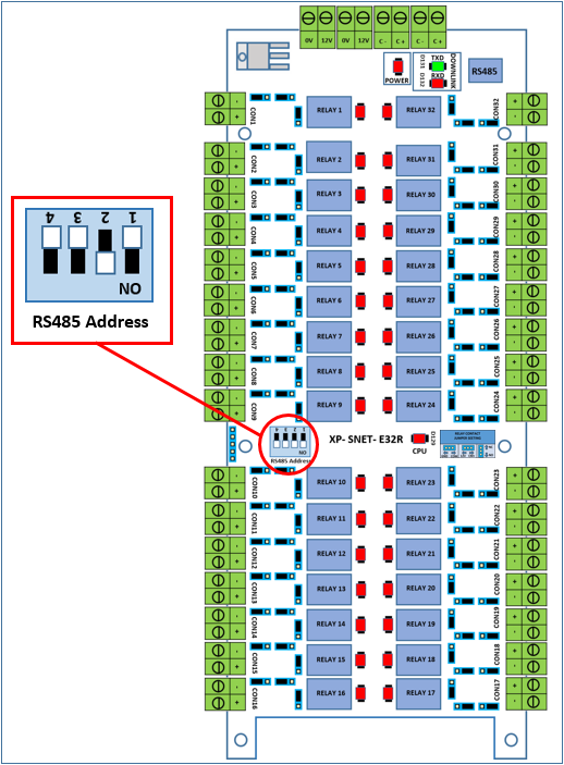
Step 1: The XP-SNET-E32R address setting for the DIP switch can be referred to as shown below:
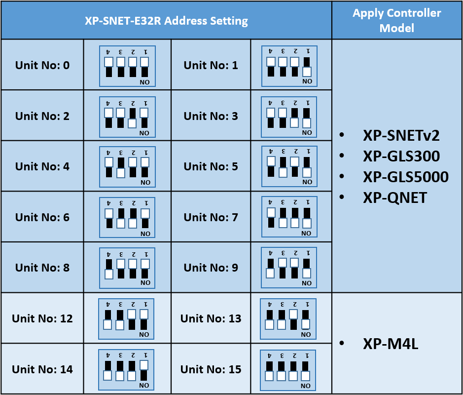
Figure 1: The DIP switches for address setting location on the XP-SNET-E32R extension board Step 2: The table below shows the different DIP switch configurations for the respective address settings:
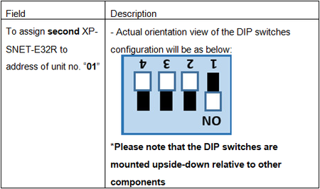
Step 3: The table below shows an example of the DIP switches settings for a XP-SNET-E32R extension board to be configured with address setting of unit no. "01":
Info The address of the extension boards must be unique (ranging from '00' to '03'), i.e.: no two extension boards in the same connection network can have the same address. . .
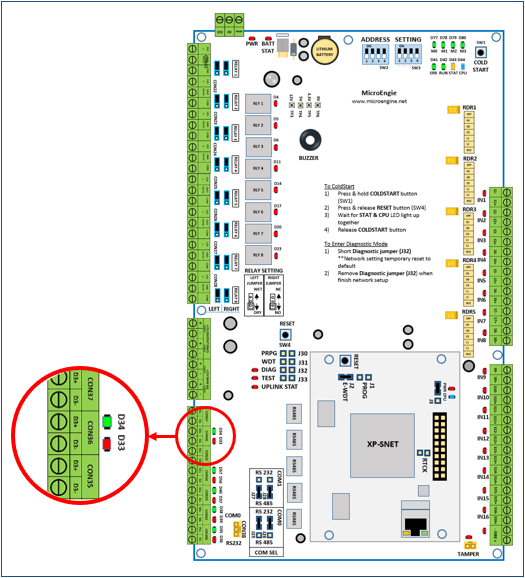
Step 1: On the XP-SNET controller, ensure that both D33 & D34 LEDs in the "Downlink" section (lower left section of XP-SNET controller) is blinking to indicate that the XP-SNET controller has successfully established communication with the XP-SNET-E32R extension board.
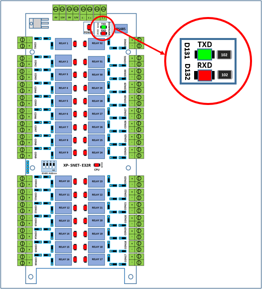
Figure 2: The D33 & D34 LEDs in the "Downlink" Step 2: On the XP-SNET-E32R extension board, ensure that both Uplink LEDs are blinking. All output relay LEDs on the XP-SNET-E32R extension board will then be turned ON.
Figure 3: The "Uplink" LEDs |
| Date Documentation: | 10/11/2021 (Rev 1.1) |
PROOF-READ
.
.
.
© MicroEngine Technology Sdn Bhd (535550-U). All rights reserved.