How to Setup Alarm Monitoring System Application Using XP-GLS5000 Controller at xPortalNet HS Server

Problem (Issue) Statement:

How to setup alarm monitoring system application using XP-GLS5000 controller at xPortalNet HS Server

Description:

A guide to configure alarm monitoring system application using XP-GLS5000 controller at xPortalNet HS Server.

Related Software:

  • xPortalNetHS v1.5.0.22

Related Hardware:

  • XP- GLS 5000 v1.16 and above
  • XP- SNET- E32R
  • XP- SNET- E248

System Application:

  • Alarm Monitoring System

Symptom and Finding:

NA

Cause:

For first time configuration for alarm monitoring system application using XP-GLS5000 controller at xPortalNet Server.

Solution:

Warning!

  • Users are not recommended to run any xPortal software in Windows XP operating system as the system is unstable

  • Users are also advised to stop the xPortal Services before shutting down the Server PC to prevent any missing transaction issues.

.

.

Summary:


Step-by-Step Guide:

  • Ensure that xPortalNet HS Services is Running:

Step 1: Open xPortalNet HS Comm Service.


Step 2: Ensure that the xPortalNet HS Comm Service Status is Running.
xPortalNet Comm Service Running Pop-up Message
Figure 1: xPortalNetComm Service Running Pop-up Message


  • To configure Connection Setup:

Step 1: Login to xPortalNet HS Server.


Step 2: Go to Server Admin Connection Setup. The Connection Setup window will be shown as below.
Connection Setup Window
Figure 2: Connection Setup window


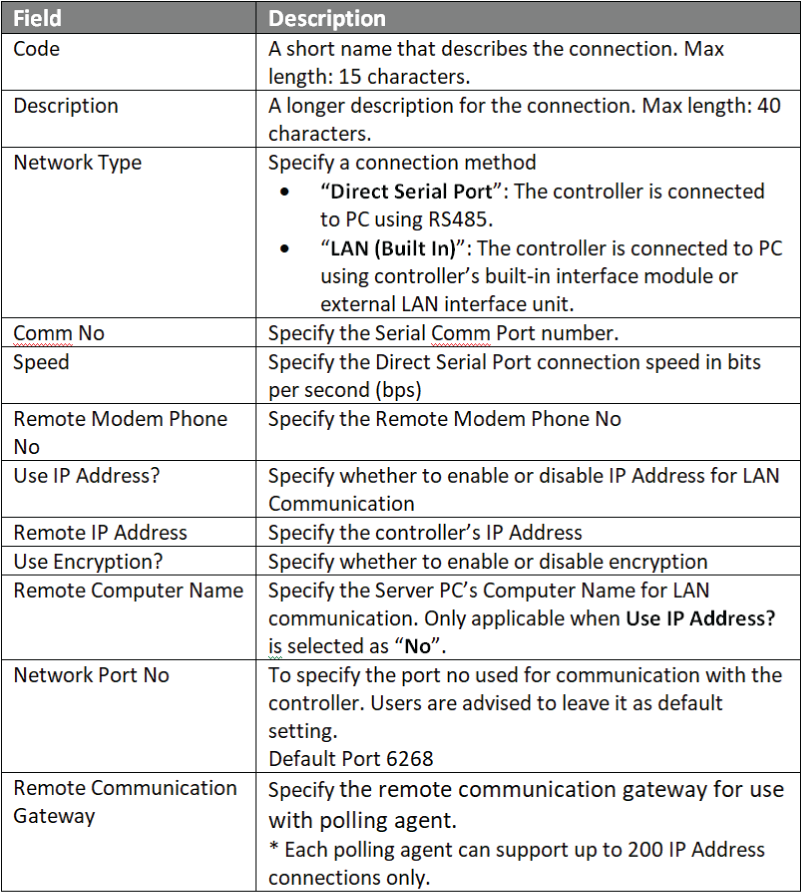
Step 3: Click Add to add a new connection. The Add Connection window will be shown as below. Fill in the respective fields and click OK to save changes
Add Connection Window
Figure 3: Add Connection window


.

.

  • To configure Controller Setup:

Step 1: Go to xPortalNet HS ServerServer Admin System Device Setup Controller. The Connection Setup window will be shown as below:
Controller Setup Window
Figure 4: Controller Setup window


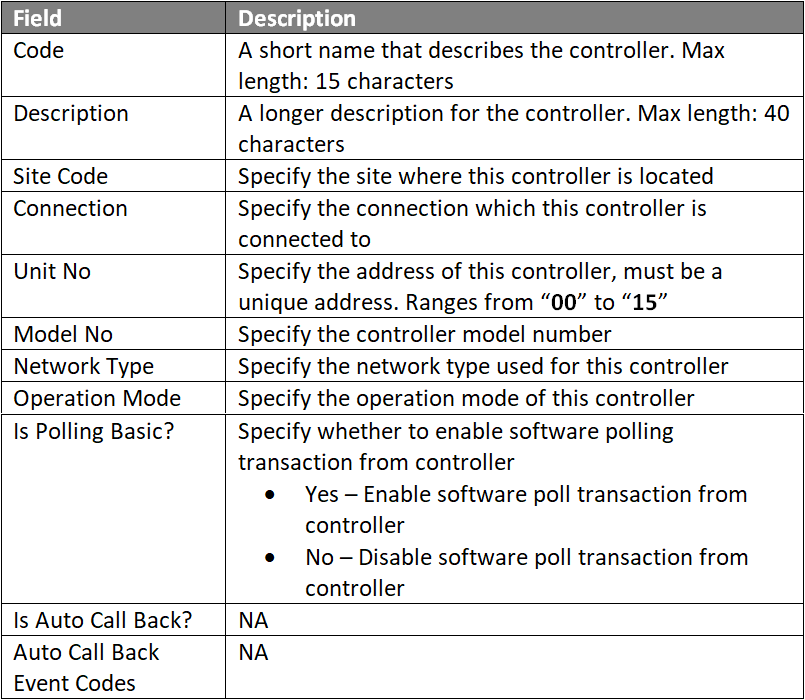
Step 2: Click Add to add a new controller device. The Add Connection Window will be shown as below. Fill up the respective field and click OK to save changes.
Add Controller Window
Figure 5: Add Controller window


Step 3: The following message window will be shown Record Added and click OKbutton.
Record Added Window
Figure 6: Record Added window
.

  • To configure Alarm Controller Setup:

Step 1: Go to xPortalNet HS ServerServer Admin System Device Setup Alarm Controller. The Alarm Controller Setup window will be shown as below:
Alarm Controller Setup Window
Figure 7: Alarm Controller Setup Window


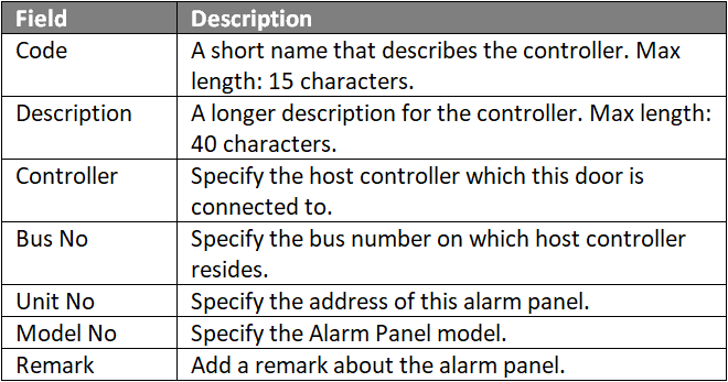
Step 2: Click Add to add a new alarm controller device. The Add Alarm Controller window will be shown as below. Fill in the respective fields and click OK to save changes.
Add Alarm Controller Window
Figure 8: Add Alarm Controller Window


Note

For internal I/O configuration on XP-GLS5000 controller, the Unit No field MUST be configured to "10"

.

.
Step 3: The following message window will be shown Record Added and click OKbutton.
Record Added Window
Figure 9: Record Added window

.

Note

Repeat steps 1 to 3 under this section for all extension boards (XP-SNET-E32R and XP-SNET-E248S) connected to the XP-GLS5000 controller board for alarm monitoring purposes.

For applications where more than one extension board is connected to the XP-GLS5000 controller board, configure the address of the alarm panel in increasing order. For example,
 - 1st extension board address = "00", 
 - 2nd extension board address = "01", 
 - 3rd extension board address = "02" , 
and so on.

In the Add Alarm Controller window, configure the Unit No. field according to the extension board address configured.


.

.

  • To configure Output Setup:

Step 1: Go to xPortalNet HS ServerServer Admin System Device Setup Output Point. The Output Setup window will be shown as below:
Output Setup Window
Figure 10: Output Setup Window


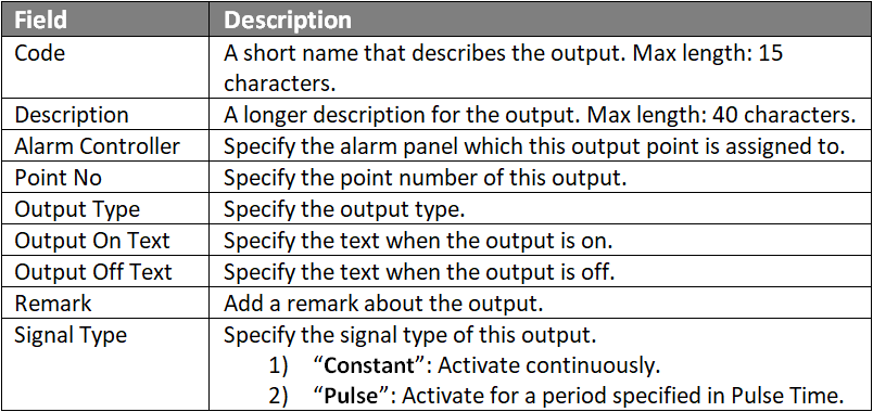
Step 2: Click Add to add a new output device. The Add Output Window will be shown as below. Fill up the respective field and click OK to save changes.
Add Output Window
Figure 11: Add Output Window


Note

The output point number starts from '0' for both extension boards XP-SNET-E32R and XP-SNET-E248.

.

.
Step 3: The following message window will be prompted to show that Record is Added. Click OK to continue.
Record Added Window

.

.

  • To configure Input Setup:

Step 1:Go to xPortalNet HS ServerServer Admin System Device Setup Input Point. The Input Setup window will be shown as below:
Input Setup Window
Figure 13: Input Setup Window


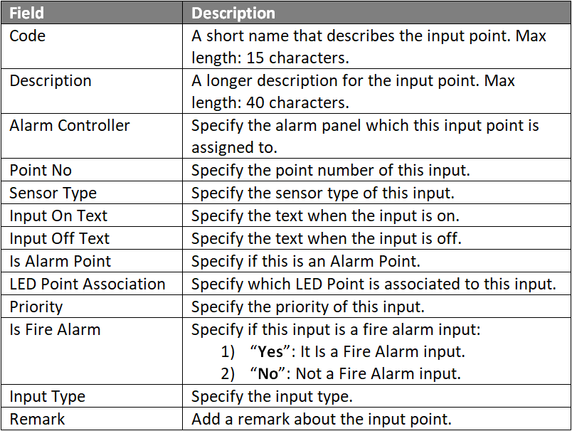
Step 2: Click Add to add a new input device. The Add Input window will be shown as below. Fill up the respective field and click OK to save changes.
Add Input Window
Figure 14: Add Input Window


Note

The input point number starts from '0' for the XP-SNET-E248 extension board.

.

.

Step 3: The following message window will be shown Record Added. Click OKto continue.
Record Added Window
Figure 15: Record Added Window


Step 4: Users can then proceed to create an Instruction Control to configure the relationship between the Inputs and Outputs.

Common Issue

NA

Date Documentation:

29/5/2019

PROOF-READ

.

Related Articles.

Containing the label "xp-gls5000"

Filter by label

There are no items with the selected labels at this time.

.


.

© MicroEngine Technology Sdn Bhd (535550-U). All rights reserved.