How to Setup Gateway Configuration Using Moxa MV28 via NPort Administrator
| Problem (Issue) Statement: | How to setup Gateway Configuration using Moxa MV28 via NPort Administrator |
| Description: | Moxa MV28 is a device which allows users to convert the RS485 connection from the controllers to LAN connection when connecting to the Server PC. This device allows users to connect XP-M1000X to Server PC via LAN, as XP-M1000X controller only supports communication via RS485 connections. This article will guide users on how to setup Gateway Configuration using Moxa MV28 via NPort Administrator. |
| Related Software: |
|
| Related Hardware: |
|
| System Application: | NIL |
| Symptom and Finding: | NIL |
| Cause: | For first time guide on how to setup Gateway Configuration using Moxa MV28 via NPort Administrator. |
| Solution: | Summary: . . Step-by-step Guide:
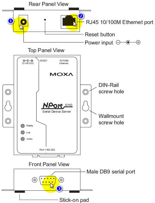
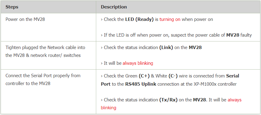
Step 1: Ensure that the Moxa MV28 is properly connected following the 3 terminals as shown in the figure below: .
. Step 2: The Moxa MV28 must be properly connected to the Server PC and be powered on before configuration on the NPort Administrator settings can be performed. . .
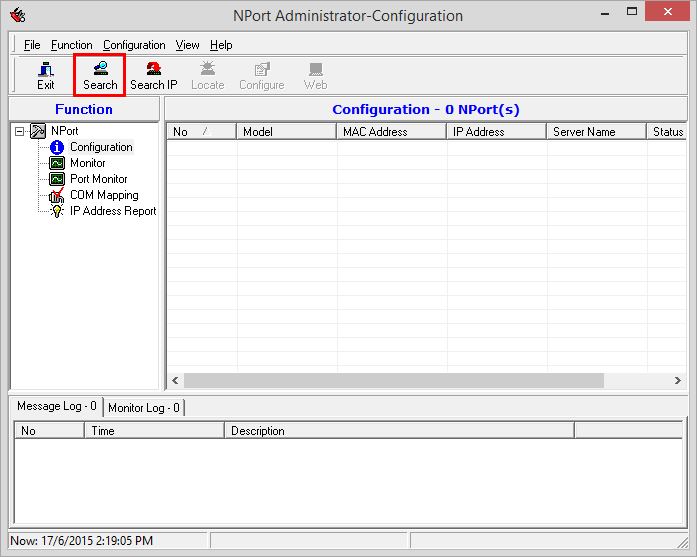
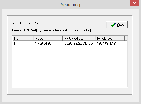
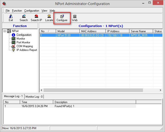
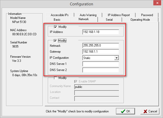
Step 1: Insert the installation CD provided together with the MV28 hardware packaging and install the program called "Npadm_Setup_Ver1.10_Build_08042811" . Step 2: Extract the file and run the installation file. . Step 3: After successful installation of the application, run the NPort Administration Suite. Users can use the Windows search function to locate the program. The NPort Administrator-Configuration window will be shown. Click Search icon. . Step 4: The Searching window will be shown as below. Wait for the search process to complete. . Step 5: Once the searching is completed, the NPort Administrator-Configuration window will be shown again, with the discovered Moxa MV28 connection. Select the respective Moxa MV28 and click Configure icon. . Step 6: The Configuration window will then be shown. Select the Network tab and configure the settings accordingly. .
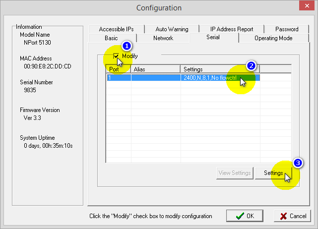
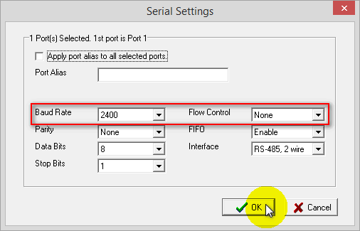
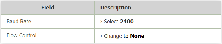
. Step 7: Next, click on the Serial tab. Tick the Modify tickbox > select the available port > click Setting. . Step 8: The Serial Settings window will then be shown. Configure the Baud Rate and Flow Control settings as per the table that follows: .
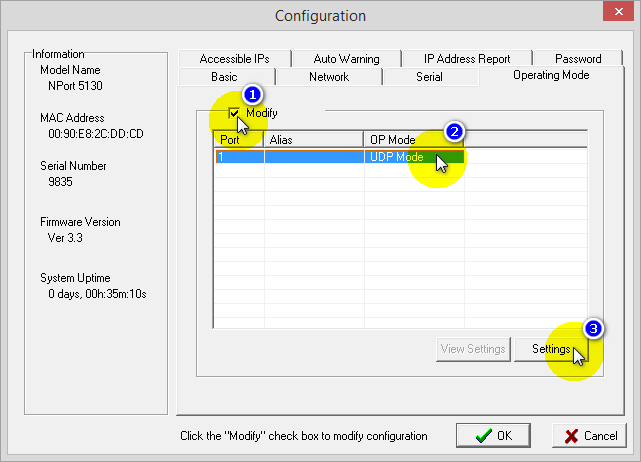
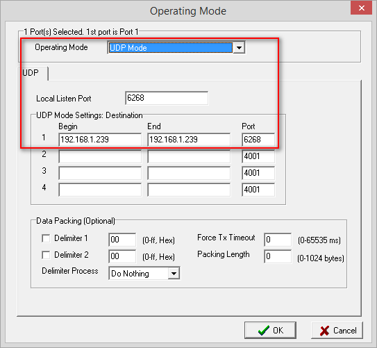
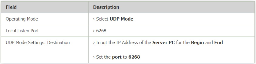
. Step 9: Click on the Operating Mode tab. Tick the Modify checkbox and click Setting. . Step 10: The Operating Mode window will then be shown. Configure the window according to the table that follows. .
. Step 11: Once all the settings for the tabs mentioned in this sections have been configured, click OK to save the changes. The configuration for the Moxa MV28 has been completed. . .
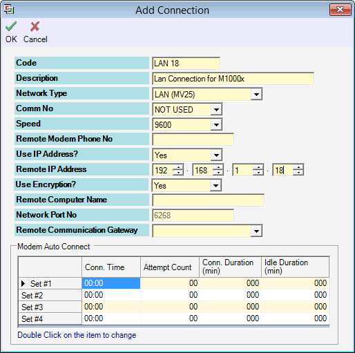
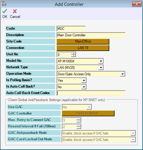
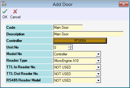
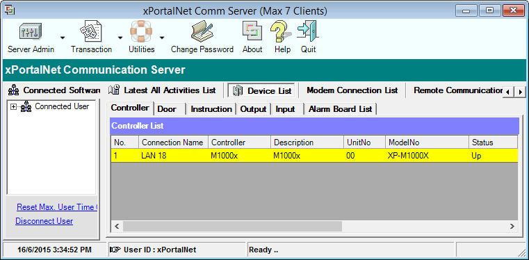
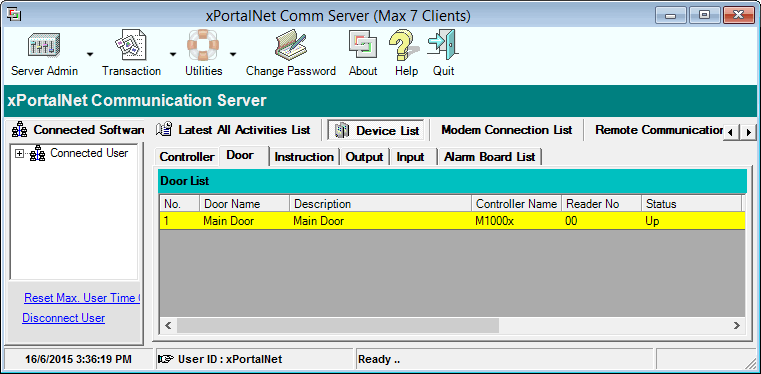
Step 1: Go to xPortalNet Server > Server Admin > Connection Setup > Add. The Add Connection window will be shown. Configure the Remote IP Address using the same IP address as configured in step 6 of the previous section. Click OK to save the changes. . Step 2: Go to xPortalNet Server > Server Admin > System Device Setup > Controller > Add. The Add Controller window will be shown. Select the correct Connection as configured in step 1 above, select the correct Model No. of the controller and the Network Type as "LAN (MV25)". Click OK to save the changes. . Step 3: Go to xPortalNet Server > Server Admin > System Device Setup > Door > Add. The Add Door window will then be shown. Set the Unit No as "0" as this controller is a single-door controller. Click OK to save the changes. . Step 4: At the software's home window, click on the Device List tab. Observe and ensure that the controller and door statuses are shown as "Up". .
|
| Common Issues: | NIL |
| Porting Date: | 6/11/2019 |

PROOF-READ
.
.
.
© MicroEngine Technology Sdn Bhd (535550-U). All rights reserved.