How to Configure the Floor Plan in xPortalNet Software
Problem (Issue) Statement: | How to Configure the Floor Plan in xPortalNet Software |
Description: | A guide to configure Floor Plan in xPortalNet software. A floor plan is a scale diagram of the arrangement of rooms in one storey of a building. User also can get the real-time status of installed devices from the Floor Plan. |
Related Software: | xPortalNet v1.5.0.150 or higher |
Related Hardware: | NIL |
System Application: | Door Access System |
Symptom and Finding: | NIL |
Cause: | For first time guide to configure the Floor Plan in xPortalNet software. |
Solution: | Warning!
. . Summary
. Step-by-step Guide:
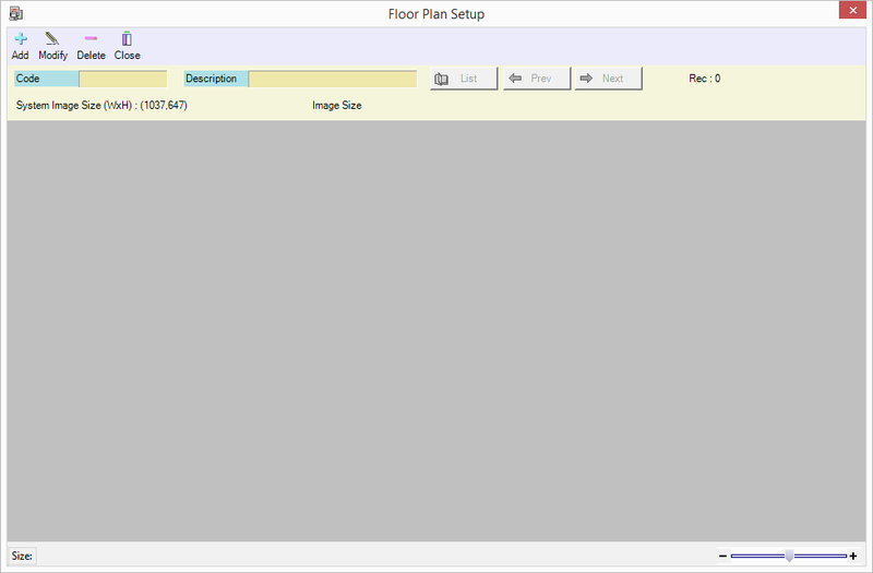
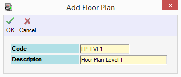
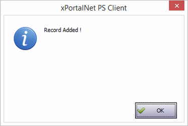
In these steps, user will be guided to create new Floor Plan record. Step 1: Login to xPortalNet Client. Step 2: Go to Data Setup > System Setting > Floor Plan Configuration > Floor Plan. Step 3: The following window will be shown. Click Add to create new Floor Plan. Step 4: Fill in the Code and Description of the Floor Plan. Then click OK. Step 5: "Record Added !" message will be shown. Click OK.
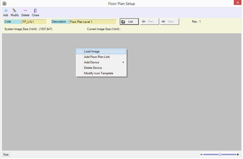
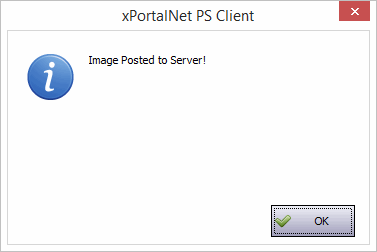
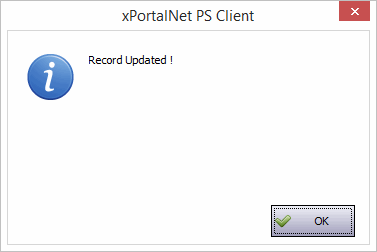
In these steps, user will be guided to add the Floor Plan image. Step 1: Right click on the grey canvas. Select Load Image. Step 2: Browse for the Floor Plan image from your image directory and click Open to load the image. Step 3: "Image Posted to Server !" message will be shown. Click OK. Step 4: "Record Updated !" message will then be shown. Click OK. Info If user wish to update / change the Floor Plan Image, user have to use the "Load Image" function. It will replace the existing Floor Plan image accordingly.
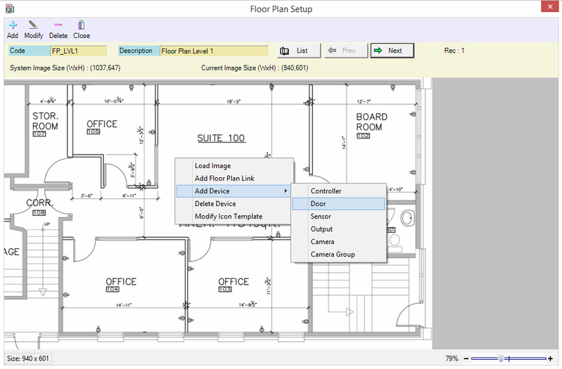
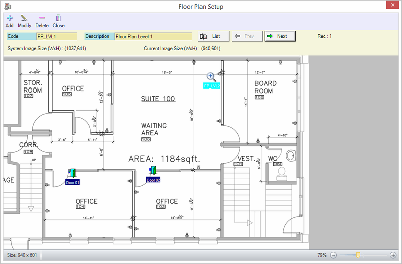
In these steps, user will be guided to add devices to the Floor Plan image. This function is to indicate the respective floors where the device is located for easy monitoring. User can monitor the statuses of the devices in real-time from the Floor Plan tab. The device must be added prior to configuring these steps. Step 1: Right click on the Floor Plan image. Select Add Device. Step 2: Select which device to be added into the Floor Plan.
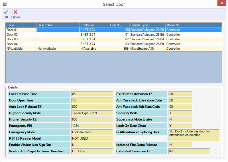
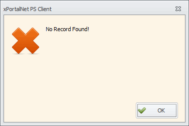
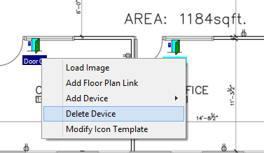
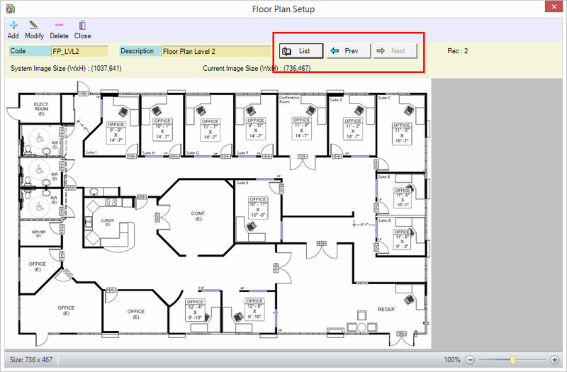
Step 3: Browse for the device Code from the list and click OK. Step 4: If the device settings are yet to be configured, user will get this message. Please configure the device in advanced. Step 5: If user wish to delete the device, right click on the device icon and select Delete Device. Step 6: User can use the List / Prev / Next button to navigate to other Floor Plan created and then add the device.
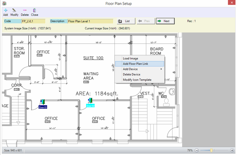
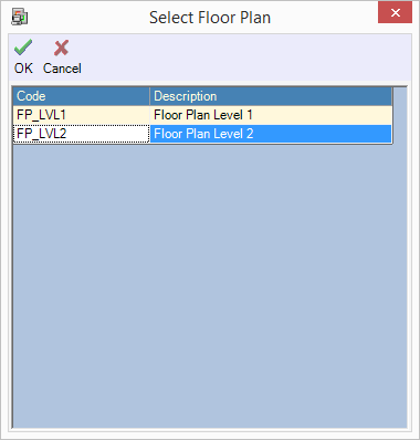
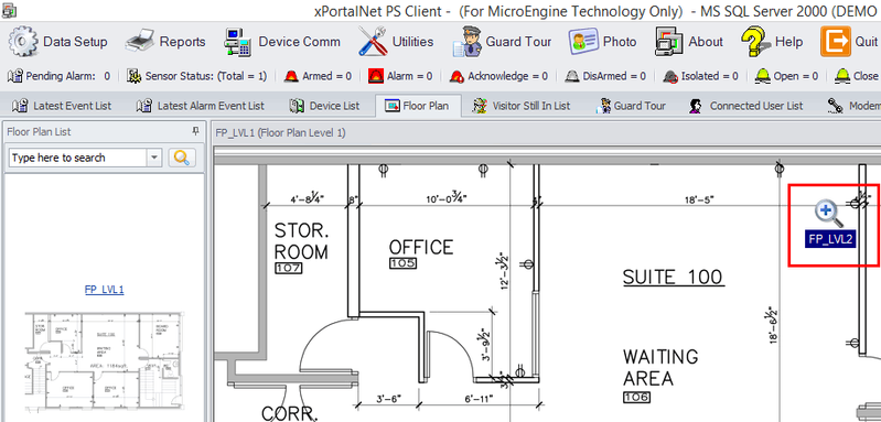
In these steps, user will be guided to add the Floor Plan Link. The link can be used to navigate from one floor plan to a different floor plan. Step 1: Right click on the Floor Plan image. Select Add Floor Plan Link. Step 2: Select which Floor Plan to be linked. Then click OK. Step 3: The Floor Plan Link is successfully added into the Floor Plan.
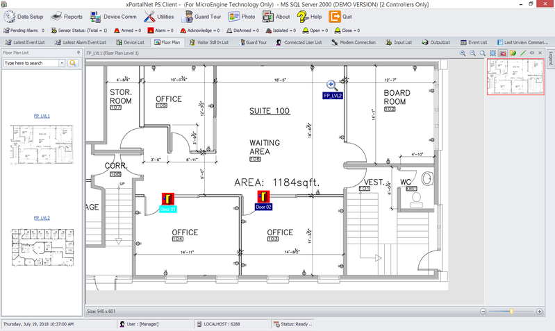
In these steps, user will be guided on how to navigate the Floor Plan. Step 1: Go to the Client main page. Click Floor Plan tab.
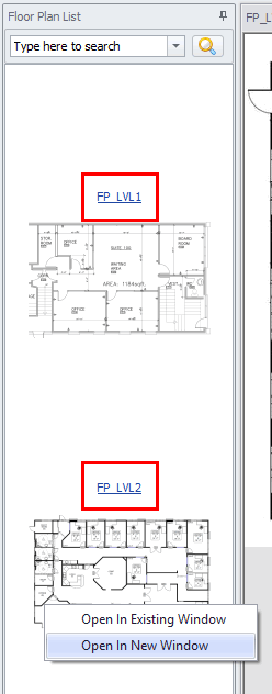
Step 2: Use the Legend tab to know what is the current device status indicated. Step 3: To open other Floor Plan, there are 2 options provided as below:
Step 4: If user has added the Floor Plan Link into the Floor Plan, simply click the link and it will jump to the specified Floor Plan. Step 5: The following ribbon can be used as follow:
|
Document Date | 19/07/2018 (Rev 1.0) |
PROOF-READ
.
.
.
Related content
© MicroEngine Technology Sdn Bhd (535550-U). All rights reserved.
