How to Connect Fire Alarm Signal to XP-GT3200 Controllers

How to Connect Fire Alarm Signal to XP-GT3200 Controllers

Problem (Issue) Statement:

How to connect fire alarm signal to XP-GT3200 controllers

Description:

A guide to connect fire alarm signal for XP-GT3200 controllers.

Related Software:

NA

Related Hardware:

  • XP-GT3200LE v3.21.0

  • XP-GT3200L v3.00.

  • XP-GT3200LABX v3.00.

  • MAS- RBT v2.10 above.

System Application:

Door Access System

Symptom and Finding:

NA

Cause:

For first time hardware wiring connection for fire alarm signal for XP-GT3200 controllers.

Solution:

Summary:

.

Step-by-step Guide:

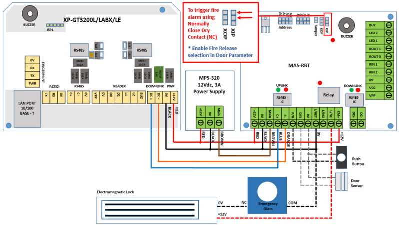
  • To follow wiring diagram as below:

Step 1: Wiring diagram XP-GT3200 controller – Fire Alarm signal connection.


Figure 1: Wiring Diagram for Fire Alarm Signal Connection to XP-GT3200 Controller
.

.

  • To enable fire alarm release:

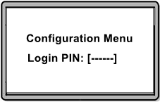
Step 1: After completing the fire alarm wiring termination, enter Configuration Menu to enable fire release setting at XP-GT3200 controller. Press *** and key in 6-digits MasterPIN.


Figure 2: Entering 6-digits MasterPIN


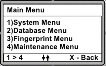
Step 2: Upon entering Configuration Menu, the Main Menu layout will be shown as below.


Figure 3: Main Menu Layout


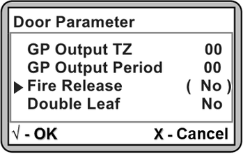
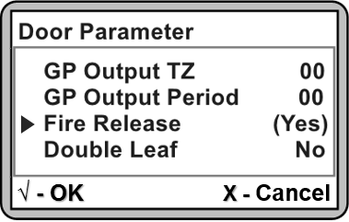
Step 3: Press 1 for System Menu > 2 for Door Parameter > Press DOWN arrow key until the parameter of Fire Release is shown. Press to change the setting as shown below.


Figure 4: Fire Release Parameter


Step 4: To enable the Fire Release feature, press UP or DOWN arrow key to change the parameter setting to "Yes" and press again.


Figure 5: Changing the Setting for Fire Release Parameter


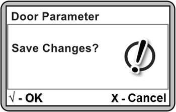
Step 5: Press X to exit from the Door Parameter menu. The following window will then be shown to confirm saving the changes. Press to confirm saving the changes.


Figure 6: Save Changes Window


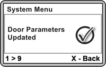
Step 6: The following window will be shown to confirm that the Door Parameters are Updated. Please wait for the controller to revert back to home window (Idle Mode).


Figure 7: Door Parameters Updated Window


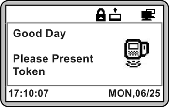
Step 7: The controller will automatically revert back to the home window (Idle Mode).


Figure 8: Home Window (Idle Mode)
.

.

  • To observe software response after triggering fire alarm signal:

Step 1: Users can test the programmed setup by triggering the fire alarm signal. The correct response observed from the hardware should be as follows:

  1. Electomagnetic lock will be released so that door can be accessed.

  2. Padlock icon on XP-GT controller's LCD screen will be shown as released to indicate that the Security status is OFF.

  3. MAS-RBT / MAS-RBU relay output LED will be turned ON to indicate that the electromagnetic lock is released.


Step 2: If the XP-GT controller is connected to the software, the Latest Event List tab will show Fire Alarm On and Door Security Off transactions.


Figure 9: Fire Alarm On and Door Security Off Transaction Logs

Step 3: When the fire alarm signal is cut off / back to normal, the Latest Event List tab will show Fire Alarm OFF transaction.

Figure 10: Fire Alarm Off Transaction Log


Warning!

After fire alarm signal is cut off, XP-GT controller does not reset back to Security On condition. Users have to set / send Security On command to XP-GT controller. 

.

.

  • To configure Door status back to Normal Operation:

Warning!

  • Users are not recommended to run any xPortal software in Windows XP operating system as the system is unstable

  • Users are also advised to stop the xPortal Services before shutting down the Server PC to prevent any missing transaction issues.

.

.

Step 1: To set Security On, enter Configuration Menu > System Menu > Door Parameter.


Step 2: Set Security OFF as "No" to enable the electromagnetic lock to secure the door.


Step 2: For software configuration to set Security On. Go to Device Comm > Send Door Command.

Figure 11: Downlaod Security On Transaction Log

Date Documentation:

25/6/2018 (Rev 1.0)

© MicroEngine Technology Sdn Bhd (535550-U). All rights reserved.