How to Setup Alarm Monitoring System Application Using XP-SNET Controller at xPortalNet Server
Problem (Issue) Statement: | How to setup alarm monitoring system application using XP-SNET controller at xPortalNet Server |
Description: | A guide to configure alarm monitoring system application using XP-SNET controller at xPortalNet Server. |
Related Software: |
|
Related Hardware: |
|
System Application: |
|
Symptom and Finding: | NA |
Cause: | For first time configuration for alarm monitoring system application using XP-SNET controller at xPortalNet Server. |
Solution: | Warning! The XP-SNET controller will not send fire alarm signal over to the connected XP-SNET-E32R and/or XP-SNET-E248 extension boards if the configuration settings for the XP-SNET controller is not completed.Complete the configuration settings for XP-SNET controller in order for XP-SNET-E32R and/or XP-SNET-E248 to respond accordingly to fire alarm signals.. . Summary
Step by Step Guide:
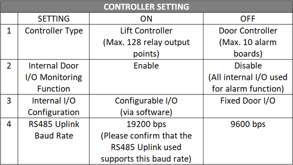
Step1: Turn "ON" DIP switch 3 under SETTING on XP-SNET controller for Alarm Monitoring Mode. Ensure that all other DIP switches remained as "OFF".
Step 1: Open xPortalNet Comm Service.
Step 1: Login to xPortalNet Server.
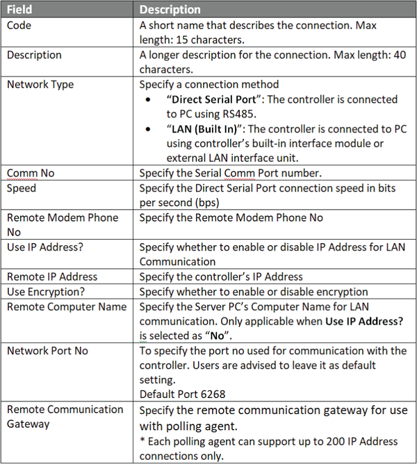
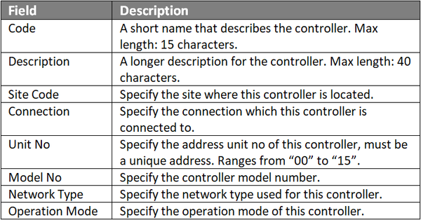
Step 1: Go to xPortalNet Server > Server Admin > System Device Setup > Controller. The Connection Setup window will be shown as below:
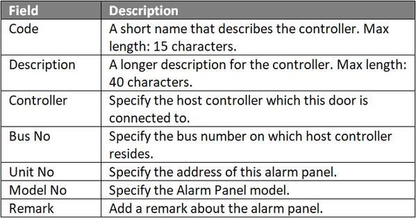
Step 1: Go to xPortalNet Server > Server Admin > System Device Setup > Alarm Controller. The Alarm Controller Setup window will be shown as below:
Note For internal I/O configuration on XP-SNET controller, the Unit No field MUST be configured to "10"
Note Repeat steps 1 to 3 under this section for all extension boards (XP-SNET-E32R and XP-SNET-E248S) connected to the XP-GLS5000 controller board for alarm monitoring purposes. For applications where more than one extension board is connected to the XP-GLS5000 controller board, configure the address of the alarm panel in increasing order. For example, In the Add Alarm Controller window, configure the Unit No. field according to the extension board address configured. . .
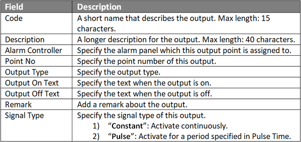
Step 1: Go to xPortalNet Server > Server Admin > System Device Setup > Output Point. The Output Setup window will be shown as below:
Note The output point number starts from "0" for both extension boards XP-SNET-E32R and XP-SNET-E248.
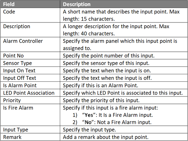
Step 1: Go to xPortalNet Server > Server Admin > System Device Setup > Input Point. The Input Setup window will be shown as below:
Note The input point number starts from "0" for the XP-SNET-E248 extension board.
Knowledge Base Link Users can refer to How to Configure Instruction Control for Alarm Monitoring System Application at xPortalNet Clientfor the complete procedures. |
Date Documentation: | 23/5/2018 (Rev 1.0) |


PROOF-READ
.
.
.
© MicroEngine Technology Sdn Bhd (535550-U). All rights reserved.