How to Connect XP-SNET Controller with XP-SNET-E248 or XP-SNET-E32R Extension Board for Alarm Monitoring System Application
Problem (Issue) Statement: | How to connect XP-SNET controller with XP-SNET-E248 / XP-SNET-E32R extension board for Alarm Monitoring System application |
Description: | A guide to connect XP-SNET controller to XP-SNET-E248 / XP-SNET-E32R extension board for Alarm Monitoring System application. |
Related Software: | NA |
Related Hardware: |
|
System Application: |
|
Symptom and Finding: | NA |
Cause: | For first time connection between XP-SNET controller with XP-SNET-E248 / XP-SNET-E32R extension board for Alarm Monitoring System application. |
Solution: | Warning! The XP-SNET controller will not send fire alarm signal over to the connected XP-SNET-E32R and/or XP-SNET-E248 extension boards if the configuration settings for the XP-SNET controller is not completed.Complete the configuration settings for XP-SNET controller in order for XP-SNET-E32R and/or XP-SNET-E248 to respond accordingly to fire alarm signals.. . Summary
Step-by-step Guide:
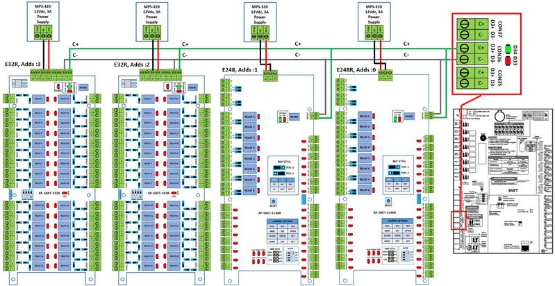
Step 1: Please follow the wiring diagram as shown below: Note The address of the extension boards must be unique (ranging from '00' to '03'), i.e.: no two extension boards in the same connection network can have the same address. . . Warning! 1 unit of XP-SNET controller is able to support up to a maximum of 128 units of input points and 128 units of output relays. . . Step 2: Users can proceed to configure the address settings for the extension boards to facilitate communication in the network. . .
Step 1: For XP-SNET-E248 extension board, Knowledge Base Link Users can refer to How to Configure Address Unit no on XP-SNET-E248 Extension Board for the complete procedures to configure address setting for XP-SNET-E248 . . Step 2: For XP-SNET-E32R extension board, Knowledge Base Link Users can refer to How to Configure Address Unit No on XP-SNET-E32R Extension Board for the complete procedures to configure address setting for XP-SNET-E32R . .
Step 1: On the XP-SNET controller, ensure that both D33 & D34 LEDs in the "Downlink" section (lower left section of XP-SNET controller) is blinking to indicate that the XP-SNET controller has successfully established communication with the XP-SNET-E248 / XP-SNET-E32R extension board. . Step 3: Download the door settings to the controller to perform the full functional tests for the system. Knowledge Base Link Users may refer to How to Send or Download Data to the Controller for the complete steps to download door settings to the controller. |
Date Documentation: | 19/6/2018 (Rev 1.1) |
PROOF-READ
.
.
.
© MicroEngine Technology Sdn Bhd (535550-U). All rights reserved.