.
.
.
.
Step 1: Open xPortalNet Comm Service.
.
Step 2: Ensure that the xPortalNet Comm Service Status is Running.

Figure 1: xPortalNet Comm Service Running pop-up message
.
Step 3: Right-click the xPortalNet Comm Service icon at the notification bar, click Check Service Info and verify that the software detects the plugged in USB license key.

Figure 2: Valid software license key detected indication
.
.
Step 1: Assign static IP address for XP-M2000i / XP-M2300i controller via web diagnostic.
.
.
.
Step 2: For Connection setup, open xPortalNet Server > Server Admin > Connection Setup. The Connection Setup window shown as below.

Figure 3: Connection Setup window
.
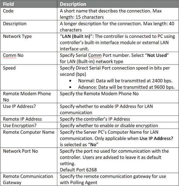
Step 3: Click Add to add a new connection. The Add Connection window will be shown as below. Click OK to save the changes.

Figure 4: Add Connection window
.
.
Step 4: For Controller Setup, go to Server Admin > System Device Setup > Controller. The Controller Setup window will be shown as below:

Figure 5: Controller Setup window
.
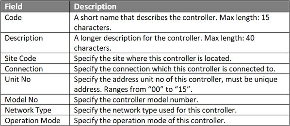
Step 5: Click Add to add a new controller. The Add Controller window will be shown as below. Click OK to save the changes.

Figure 6: Add Controller window
.
.
Step 6: For Door Setup, go to Server Admin > System Device Setup > Door. The Door Setup window shown as below

Figure 7: Door Setup window
.
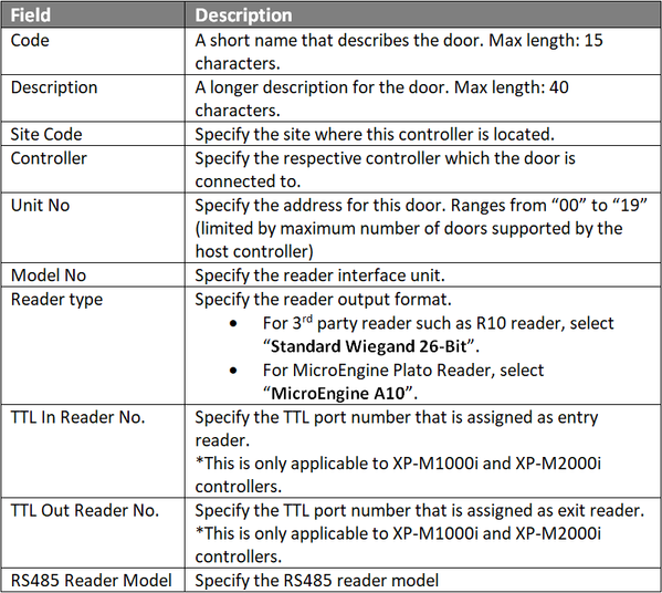
Step 7: Click Add, the Add Door window will be prompted by xPortalNet software as shown below. Click OK to save the changes.

Figure 8: Add Door window
.
.
.
.
Step 7: The following message window will be shown to indicate that the Record is Added. Click OK to continue.

Figure 9: Record Added window
.
Step 8: The Connection, Controller, and Door settings are configured. Users can now observe the controller and door Status at Device List.
.
.
Step 1: To use the controller Search function, go to xPortalNet Server > System Device Setup > Controller > Search.

Figure 10: The Search icon
.
Step 2: The Controller Discovery window will be shown as below. Once the connected controllers are discovered, select the controller to be configured and click Configure Controller.

Figure 11: Controller Discovery window
.
Step 3: The Configure Controller window will be shown as below.Users are advised to re-assign the controller's IP address, subnet mask, gateway and Server IP address following the site requirements.

Figure 12: Configure Controller window
.
Step 4: After clicking OK, xPortalNet software will prompt users to enter the web diagnostic password to proceed to update changed settings.

Figure 13: Software prompting to enter web diagnostic password
.
Step 5: The following message window will be shown once all settings are updated. Click OK.

Figure 14: Settings are updated successfully! message window
.
Step 6: The following message window will then be shown as the software is retrieving controller info.

Figure 15: Retrieving Controller Info message window
.
Step 7: The Controller Discovery window will then be shown again. Select the same controller and click Add Controller to continue.

Figure 16: Controller Discovery window
.
Step 8: The Connection Setup window will be shown as below.
Figure 17: Connection Setup window
.
Step 9: Click Add to add a new connection. The Add Connection window will be shown as below. Click OK to save the changes.

Figure 18: Add Connection window
.
.
Step 10: The software will automatically prompt the Controller Setup window as shown below:

Figure 19: Controller Setup window
.
Step 11: Click Add to add a new controller. The Add Controller window will be shown as below. Click OK to save the changes.

Figure 20: Add Controller window
.
.
Step 12: The following message window will be shown to indicate that the Record is Added. Click OK to continue.

Figure 21: Record Added message window
.
Step 13: For Door Setup, go to xPortalNet Server > System Device Setup > Door. The Door Setup window will be shown as below:

Figure 22: Door Setup window
.
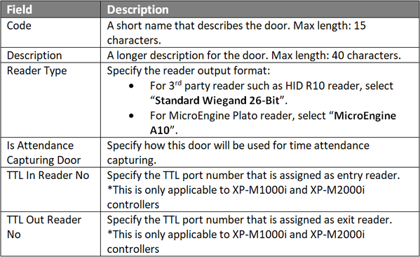
Step 14: Click Add to add a new door. The Add Door window will be shown as below. Fill up the door details as below and click OK to save the changes.

Figure 23: Add Door window
.
.
.
.
Step 15: The following message window will be shown to indicate that the software is refreshing the connection. Click OK.

Figure 24: Refresh Connection message window
.
Step 16: The Connection, Controller, and Door settings are configured. Users can now observe the controller and door Status at Device List.
.
.
Step 1: After completing the Connection, Controller and Door settings using EITHER of the two methods, users can now check the status of the controller and door.
.
Step 2: To check the status of the controller, go to xPortalNet Server> Device List > Controller List to verify that the controller Status is Up.

Figure 25: Controller List under Device List tab
.
Step 3: To check the status of the door,go to xPortalNet Server> Devices List > Door Listto verify that the door StatusisUp.

Figure 26: Door List under Device List tab