How to Configure and Terminate Wiring Connection to Monitor Emergency Break Glass Status on XP-M1000i and XP-M2000i

Problem (Issue) Statement:

Wiring termination for emergency break glass to XP-M1000i and XP-M2000i controllers and configuring the extra input on controllers to monitor emergency break glass (EBG) status on xPortalNet software.
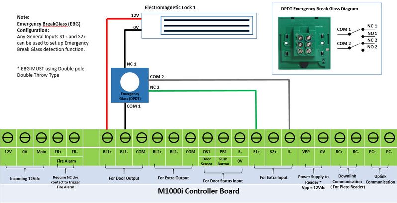
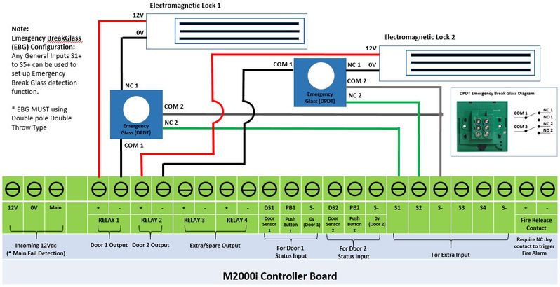
Description:

Emergency break glasses were installed at site as a measure to ensure that the system is fail-safe in the event of an emergency. When the glass is broken, the emergency break glass will cut power to the electromagnetic lock allowing users to escape using the opened door.

To prevent misuse of the emergency break glass, the xPortalNet software can be used to monitor the device status. Under this configuration, if the emergency break glass is activated, the software will be prompted of the event and a transaction will be recorded.

Related Software:

/wiki/spaces/SRN/pages/97321377

Related Hardware:

/wiki/spaces/FRN/pages/103711015, XP-M2000i v6.16 and Plato reader C80s v6.07.

System Application:

Door Access System

Symptom and Finding:

NA

Cause:

This is a guide on how to terminate the SPDT emergency break glass device to the extra input point on the controllers; and to configure the extra input to monitor the emergency break glass status at the xPortalNet software.

Solution:

Warning!

We do not recommend controllers and PC communication to be connected via Wifi (using Wifi dongles) as Wifi connection is unstable and can make controller statuses be shown as "Down".

.

.

Summary 

  • For the hardware wiring termination of the emergency break glass to the controllers, users can refer to the wiring diagrams for the XP-M1000i and XP-M2000i as attached below: 


Figure 1: Wiring diagram for XP-M1000i controller with emergency break glass and
electromagnetic lock

 
Figure 2: Wiring diagram for XP-M2000i controller with emergency break glass and
electromagnetic lock

  • To configure xPortalNet software to monitor the status of the emergency break glass.

.

.

Step-by-step Guide:

  • To configure xPortalNet software to monitor the status of the emergency break glass:

Warning!

  • Users are not recommended to run any xPortal software in Windows XP operating system as the system is unstable

  • Users are also advised to stop the xPortal Services before shutting down the Server PC to prevent any missing transaction issues.

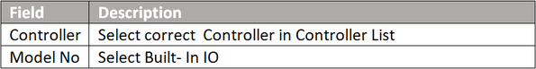
.

.

Step 1: Setup Alarm Controller.

  1. After adding Connection, Controller and Door, users must add an alarm controller. Go to xPortalNet Server > Server Admin > System Device Setup > Alarm Controller.
  2. The Alarm Controller Setup window will be shown. Click Add.

    Alarm Controller Setup Window
    Figure 3: Alarm Controller Setup Window
  3. The Add Alarm Controller window will be shown. Fill the details and take note on the highlighted fields.

    Add Alarm Controller Window
    Figure 4: Add Alarm Controller Setup

    Info

    XP-M1000i & XP-M2000i controller does not support any extension IO board. Both controllers have built-in spare IO for monitoring purposes.

    *Extra inputs are support Normally Close (NO) only.

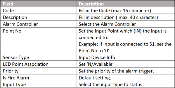
Step 2: Add Input Point

  1. Go to xPortalNet Server > Server Admin System Device Setup Input Point.
  2. The Input Setup window will be shown. Click Add.

    Input Setup Window
    Figure 5: Input Setup Window
  3. The Add Input window will be shown. Fill the details according to the table that follows.

    Add Input Window
    Figure 6: Add input point window


Step 3: Send door setting to controller 

  1. After finishing the configuration settings, please send the door settings to the controller by following the steps below.
  2. Go to xPortalNet Client > Device Comm > Send Door Setting. The Send Door Controller Settings window will be shown:

    Send Door Controller Settings Window
    Figure 7: Send Door Controller Setting Window
  3. Users should send the Alarm Controller settings first, before sending the Inputs settings to the controller, as stipulated by the numbering sequence on the figure above.


Step 4: Activated emergency break glass will trigger the subsequently connected inputs. The triggering of the input will be recorded in the 'Latest Event List' and the Input List tab.

Latest Event List Window

Figure 8: Latest Event List Window

Date Documentation:

19/6/2018 (Rev 1.1)

PROOF-READ

.

.


.

© MicroEngine Technology Sdn Bhd (535550-U). All rights reserved.