Step 1: Assign static IP address for XP-M1000i / XP-M1300i controller via web diagnostic.
Step 2: For Connection setup, open Control Panel > System Setting > Connection.

Figure 2: Connection icon in System Setting menu
Step 3: The Connection Setup window will be shown as below:

Figure 3: Connection Setup window
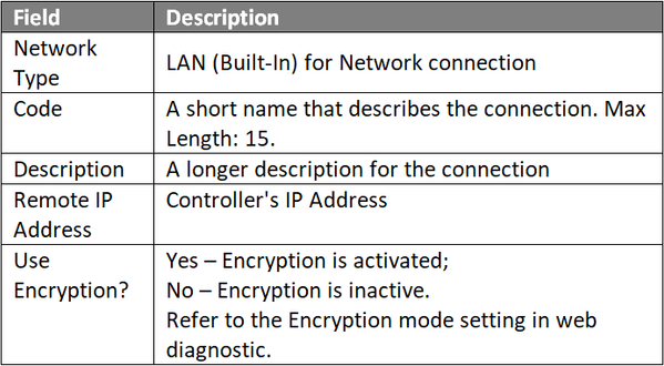
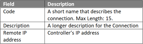
Step 4: Click Add to add a new connection. The Add Connection window will be shown as below. Click OK to save the changes.

Figure 4: Add Connection window
Step 5: For Controller Setup, back at System Setting menu, click Controller icon.

Figure 5: Controller icon in System Setting menu
Step 6: The Controller Setup window will be shown as below:

Figure 6: Controller Setup window
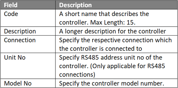
Step 7: Click Add to add a new controller. The Add Controller window will be shown as below. Click OK to save the changes.

Figure 7: Add Controller window
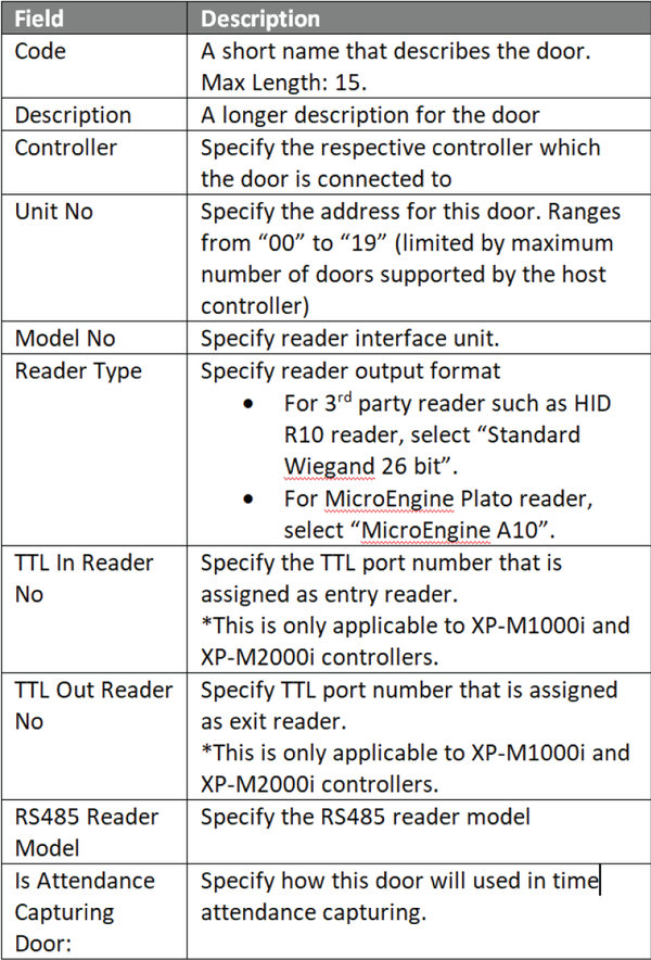
Step 8: For Door Setup, the Add Door window will be prompted by xPortal3000 software as shown below. Click OK to save the changes.

Figure 8: Add Door window that is automatically prompted by xPortal3000 software
Step 9: The following message window will be shown to indicate that the software is refreshing the newly added controller records:

Figure 9: Refreshing controller record message window
Step 10: The Connection, Controller, and Door settings are configured. Users can now observe the Controller and Door Status at Device List.
Step 1: At xPortal3000 home window, click Device Lookup icon:

Figure 10: Device Lookup icon at home window
Step 2: The Controller Discovery and Device Discovery windows will be shown as below. Once the connected controllers are discovered, select the controller to be configured and click Configure Controller.

Figure 11: Controller Discovery and Device Discovery window
Step 3: The Configure Controller window will be shown as below. Users are advised to re-assign the controller's IP address, subnet mask, gateway and Server IP address following the site requirements.

Figure 12: Configure Controller window
Step 4: After clicking OK, xPortal3000 software will prompt users to enter the web diagnostic password to proceed to update changed settings.

Figure 13: Software prompting to enter web diagnostic password
Step 5: The following message window will be shown once all settings are updated. Click OK.

Figure 14: Settings are updated successfully! message window
Step 6: xPortal3000 software will then show this message window to prompt users to add the controller to the software database. Click Yes to continue.

Figure 15: xPortal3000 prompts users to add the controller to software database
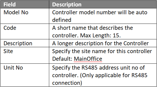
Step 7: The Controller Wizard will be shown. At the Controller Settings window, fill up the respective fields. Click Next to continue.

Figure 16: Controller Settings window
Step 8: The Connection Settings window will then be shown. Fill up the respective fields and click Next to continue.

Figure 17: Connection Settings window
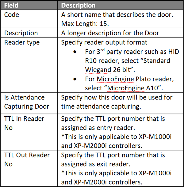
Step 9: At the Door Settings window, fill up the door details as per below. Click Next to continue.

Figure 18: Door Settings window
 .
.
Step 10: The Door Access Assignment window will be shown. Check the checkbox for "Skip this step. I will setup later" to temporarily skip the setup. Click Next to continue.

Figure 19: Door Access Assignment window
Step 11: The Alarm Panel And Input/Output Settings window will then be shown. Check the checkbox for "Skip this step. I will setup later" to temporarily skip the setup. Click Next to continue.

Figure 20: Alarm Panel And Input/Output Settings window
Step 12: At the Summary window, review all the configuration settings for Controller, Connection, and Door settings to ensure that all settings are correct before clicking Next to proceed.

Figure 21: Summary window
Step 13: The following message window will be shown while software is updating the device settings into the database. Please wait until the process is completed.

Figure 22: Refreshing controller record message window
Step 14: The Connection, Controller, and Door settings are configured. Users can now observe the controller and door Status at Device List.
Step 1: After completing the Connection, Controller and Door settings using EITHER of the two methods, users can now check the status of the controller and door.
Step 2: To check the status of the controller, go to Device List > Controller List to verify that the controller Status is Up.

Figure 23: Controller List under Device List
Step 3: To check the status of the door, go to Devices List > Door List to verify that the door Status is Up.

Figure 24: Door List under Device List
