How to Configure Connection, Controller, and Door Settings for XP-M1000i or XP-M1000i-SE21 Controller with xPortalNet Software

Problem (Issue) Statement:

How to configure Connection, Controller, and Door settings for XP-M1000i / XP-M1300i controller with xPortalNet software?

Description:

A guide to configure Connection, Controller, and Door settings for XP-M1000i / XP-M1300i controller with xPortalNet software.

Related Software:

  • xPortalNet v1.5 / v1.7 Lite
  • xPortalNet v1.5 / v1.7 Standard
  • xPortalNet v1.5 / v1.7 PS

Related Hardware:

  • XP-M1000i
  • XP-M1000i-SE21

System Application:

  • Door Access System

Symptom and Finding:

NA

Cause:

For first time configuration on Connection, Controller, and Door settings for XP-M1000i / XP-M1000i-SE21 controller with xPortalNet software.


Warning!

  • Users are not recommended to run any xPortal software in Windows XP operating system as the system is unstable

  • Users are also advised to stop the xPortal Services before shutting down the Server PC to prevent any missing transaction issues.

.

.

Warning!

We do not recommend controllers and PC communication to be connected via Wifi (using Wifi dongles) as Wifi connection is unstable and can make controller statuses be shown as "Down".

.

.

Summary


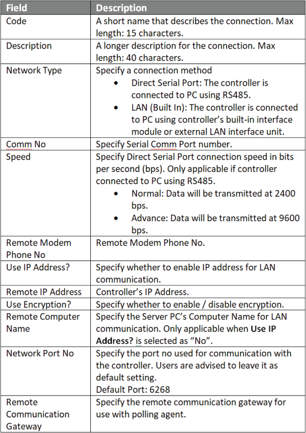
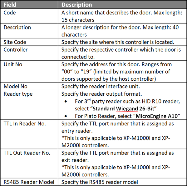
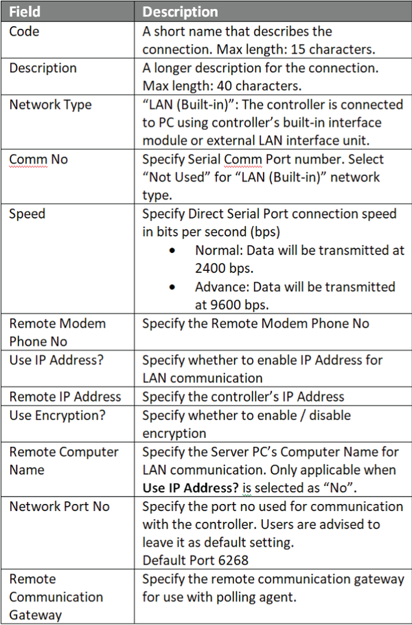
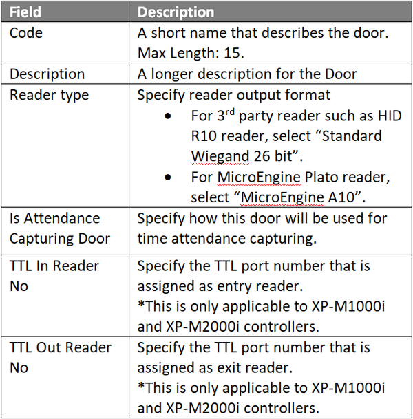
To Configure Connection, Controller, and Door Settings

Users can choose EITHER one of the two methods to configure the Connection, Controller, and Door settings.

.

Note

The XP-M1000i-SE21 controller does not directly support 3rd party readers. Add-on module if 3rd party card reader is required: XP-MK-WG10S

.

Step-by-step Guide:

  • Before configuring Connection, Controller, and Door settings for XP-M1000i / XP-M1000i-SE21 controller with xPortalNet, ensure that the pre-configure network connection has been complete:


Knowledge Base Link

Users may refer to How to Pre-configure Network Connection for IP Controllers for the complete pre-configuration steps.

.

.

  • To ensure that the xPortalNet Services is running and dongle license is detected as shown below:

Step 1: Open xPortalNet Comm Service.


Step 2: Ensure that the xPortalNet Comm Service Status is Running.
xPortalNet Comm Service Running Pop-up Message
Figure 1: xPortalNet Comm Service Running pop-up message


Step 3: Right-click the xPortalNet Comm Service icon at the notification bar, click Check Service Info and verify that the software detects the plugged in USB license key.
Valid Software License Key Detected Indication
Figure 2: Valid software license key detected indication
.

.

  • Method 1: To configure Connection, Controller, and Door settings manually after assigning static IP address for XP-M1000i / XP-M1000i-SE21 controller via Web Diagnostic:

Step 1: Assign static IP address for XP-M1000i / XP-M1000i-SE21 controller via web diagnostic.

.

Knowledge Base Link

Users may refer to How to Configure IP Address for IP Controllers for the complete configuration steps.

.

.
Step 2: For Connection setup, open xPortalNet Server > Server Admin > Connection Setup. The Connection Setup window will be shown as below.
Connection Setup Window
Figure 3: Connection Setup window


Step 3: Click Add to add a new connection. The Add Connection window will be shown as below. Click OK to save the changes.
Add Connection Window
Figure 4: Add Connection window


Step 4: For Controller Setup, go to Server Admin > System Device Setup > Controller. The Controller Setup window will be shown below:
Controller Setup Window
Figure 5: Controller Setup window


Step 5: Click Add to add a new controller. The Add Controller window will be shown as below. Click OK to save the changes.
Add Controller Window
Figure 6: Add Controller window


Step 6: For Door Setup, the Add Door window will be prompted by xPortalNet software as shown below. Click OK to save the changes.
Add Door Window
Figure 7: Add Door window


Note

  • TTL In / Out Reader No configuration settings are only applicable when the third party reader is connected directly to the TTL port.
  • If users are not using TTL readers, users can ignore the TTL Reader settings.

.

.
Step 7: The following message window will be shown to indicate that the Record is Added. Click OK to continue.
Record Added Window
Figure 8: Record Added window


Step 8: The Connection, Controller, and Door settings are configured. Users can now observe the controller and door Status at Device List.
.

.

  • Method 2: To configure connection, controller, and door settings using the Controller Search feature in xPortalNet:

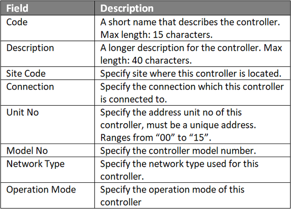
Step 1: To use the controller Search function, go to xPortalNet Server > System Device Setup > Controller > Search.
Search Icon in Controller Setup Window
Figure 9: The Search icon


Step 2: The Controller Discovery window will be shown as below. Once the connected controllers are discovered, select the controller to be configured and click Configure Controller.
Controller Discovery Window
Figure 10: Controller Discovery window


Step 3: The Configure Controller window will be shown as below. Users are advised to re-assign the controller's IP address, subnet mask, gateway and Server IP address following the site requirements.
Configure Controller Window
Figure 11: Configure Controller window


Step 4: After clicking OK, xPortalNet software will prompt users to enter the web diagnostic password to proceed to update changed settings.
Software Prompting to Enter Web Diagnostic Password
Figure 12: Software prompting to enter web diagnostic password


Step 5: The following message window will be shown once all settings are updated. Click OK.
Settings Are Updated Successfully Window
Figure 13: Settings are updated successfully! message window


Step 6: The Add Connection window will be shown. Fill up the respective fields. Click OK to continue.
Add Connection Window
Figure 14: Add Connection window


Step 7: The following message window will be shown to indicate that the Record is Added. Click OK to continue.
Record Added Window
Figure 15: Record Added message window


Step 8: The Add Controller window will be shown. Fill up the respective fields. Click OK to continue
Add Controller Window
Figure 16: Add Controller window


Step 9: The following message window will be shown to indicate that the Record is Added. Click OK to continue.
Record Added Window
Figure 17: Record Added message window


Step 10: The Add Door Setting window will then be shown. Fill up the door details as below and click OK.
Add Door Window
Figure 18: Add Door window


Note

  • TTL In/Out Readers are then connected to the respective TTL ports following the TTL In Reader No. and TTL Out Reader No. settings respectively.
  • If users are not using TTL readers, users can ignore the TTL Reader settings.

.

.
Step 10: The following window will be shown after users have configured the relevant settings. Please wait until prompt the Request submitted to refresh connection window. Click OK to continue.
Retrieving Controller Information Window
Figure 19: Retrieving Controller Information window


Refresh Connection Message Window
Figure 20: Refresh Connection message window


Step 11: The Connection, Controller, and Door settings are configured. Users can now observe the controller and door Status at Device List.

.

.

  • To observe the Controller and Door status at Device List:

Step 1: After completing the Connection, Controller and Door settings using EITHER of the two methods, users can now check the status of the controller and door.


Step 2: To check the status of the controller, go to xPortalNet Server > Device List > Controller List to verify that the controller Status is Up.
Controller List under Device List Tab
Figure 21: Controller List under Device List tab


Step 3: To check the status of the door, go to xPortalNet Server > Devices List > Door List to verify that the door Status is Up.
Door List under Device List tab
Figure 22: Door List under Device List tab

Date Documentation:

31/7/2023 (Rev 2.0)

PROOF-READ

.

.


.

© MicroEngine Technology Sdn Bhd (535550-U). All rights reserved.