.
.
.
.
Step 1: Open xPortal3000 Server Configuration Manager.
.
Step 2: Ensure that the Service State is Running:

Figure 1: Service State of the xPortal3000 Server Configuration Manager has to be in Running for xPortal3000 software to operate
.
Step 3: If the Service State is Stopped, users have to start the xPortal3000 Services by clicking Start.
.
.
Step 1: Assign static IP address for XP-M2000i / XP-M2300i controller via web diagnostic.
.
.
Step 2: For Connection setup, Open Control Panel > System Setting > Connection.

Figure 2: Connection icon in System Setting menu
.
Step 3: The Connection Setup window will be shown as below:

Figure 3: Connection Setup window
.
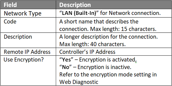
Step 4: Click Add to add a new connection. The Add Connection window will be shown as below. Fill up the respective field and click OK to save changes.

Figure 4: Add Connection window
.
.
Step 5: For Controller Setup, back at System Setting menu, click Controller icon. The Controller Setup window shown as below:

Figure 5: Controller Setup window
.
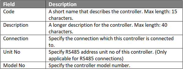
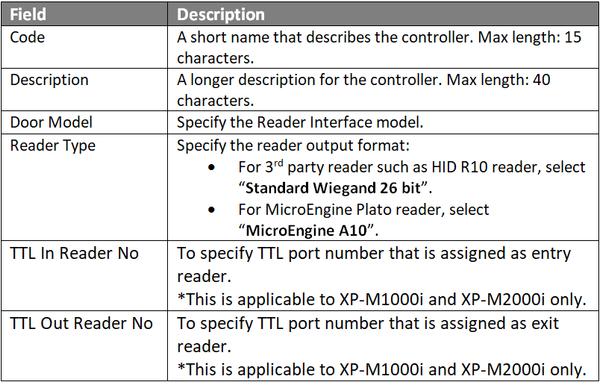
Step 6: Click Add to add a new controller. The Add Controller window will be shown as below. Fill up the respective field and click OK to save changes.

Figure 6: Add Controller window
.
.
Step 7: For Door Setup, back at System Setting menu, click Door icon. The Door Setup window will be shown as below.

Figure 7: Door Setup window
.
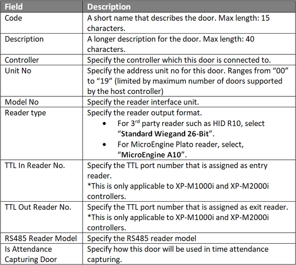
Step 8: Click Add to add a new door. The Add Door Window will be shown as below. Fill up the respective field and click OK to save changes.

Figure 8: Add Door window
.
.
.
.
Step 9: The following message window will be shown to indicate that the Record is Added. Click OK to continue.
 .
.
Figure 9: Record Added window
.
Step 10: Repeat Steps 7 and 8 if users wished to add a second door to the software database.
.
Step 11: The Connection, Controller, and Door settings are configured. Users can now observe the controller and door Status at Device List.
.
.
Step 1: At xPortal3000 home window, click Device Lookup icon:

Figure 10: Device Lookup icon at home window
.
Step 2: The Controller Discovery windows will be shown as below. Once the connected controllers are discovered, select the controller to be configured and click Configure Controller.

Figure 11: Controller Discovery window
.
Step 3: The Configure Controller window will be shown as below. Users are advised to re-assign the controller's IP address, subnet mask, gateway and Server IP address following the site requirements.

Figure 12: Configure Controller window
.
Step 4: After clicking OK, xPortal3000 software will prompt users to enter the web diagnostic password to proceed to update changed settings.

Figure 13: Software prompting to enter web diagnostic password
.
.
.
Step 5: The following message window will be shown once all settings are updated. Click OK.

Figure 14: Settings are updated successfully message window
.
Step 6: xPortal3000 software will then show this message window to prompt users to add the controller to the software database. Click Yes to continue.

Figure 15: xPortal3000 prompts users to add the controller to software database
.
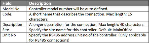
Step 7: The Controller Wizard will be shown. At the Controller Settings window, fill up the respective fields. Click Next to continue.

Figure 16: Controller Settings window
.
.
Step 8: The Connection Setting window will then be shown. Fill up respective field and click Nextto continue.

Figure 17: Connection Settings window
.

.
Step 9: At the Multi Doors Settings window, check the Is Used checkbox for respective connected doors and continue to fill up the respective fields. Click Next to continue.

Figure 18: Multi Doors Settings window
.
.
.
.
Step 10: The Door Access Assignment window will be shown. Check the checkbox for "Skip this steps, I will setup it later" to temporarily skip the setup. Click Next to continue.

Figure 19: Door Access Assignment window
.
Step 11: The Alarm Panel And Input/Output Setting window will then be shown. Check the checkbox for "Skip this steps, I will setup it later" to temporarily skip the setup. Click Next to continue.

Figure 20: Alarm Panel And Input/Output Setting window
.
Step 12: At the Summary window, review all the configuration setting for Controller, Connection, and Door Settings to ensure that all settings are correct before clicking Next to proceed.

Figure 21: Summary window
.
Step 13: The following message window will be shown while software is updating the device settings into the database, Please wait until the process is completed.

Figure 22: Refreshing controller record message window
.
Step 14: Once the software successfully updated device settings, the Delivery Report window will be shown as below. Ensure that all fields have "Send OK!" comment, indicating that the respective settings has been successfully sent to the controller. Click Close to continue.

Figure 23: Delivery Report window
.
Step 14: The following message prompt will be shown upon completing the Controller Setup Wizard window, click Finish.

Figure 24: Completing the Controller Setup Wizard window
.
Step 15: The Connection, Controller, and Door settings are configured. Users can now observe the controller and door Status at Device List.
.
.
Step 1: After completing the Connection, Controller and Door settings using EITHER of the two methods, users can now check the status of the controller and door.
.
Step 2: To check the status of the controller, go to xPortalNet Server > Device List > Controller List to verify that the controller Status is Up.

Figure 25: Controller List under Device List tab
.
Step 3: To check the status of the door,go to xPortalNet Server > Devices List > Door List to verify that the door Status is Up.

Figure 26: Door List under Device List tab