How to Configure IP Address for XP-GTR1500 or XP-GT3500 Controller

Problem (Issue) Statement:

How to configure IP address for XP-GTR1500 / XP-GT3500 controller

Description:

A guide to configure IP address for XP-GTR1500 / XP-GT3500 controller.

Related Software:

NA

Related Hardware:

  • XP-GTR1500L
  • XP-GTR1500LABX
  • XP-GT3500L
  • XP-GT3500LABX

System Application:

Single Door Access

Symptom and Finding:

NA

Cause:

For first time configuration of IP address for XP-GTR1500 / XP-GT3500 controller.

Solution:

Summary

.

To Configure IP Address:

Users can choose EITHER one of the 3 methods to configure the GT/GTR controller's IP address.

.

.

Reminder!

Method 3 is only available to xPortal3000 software.

.

.

Step-by-step Guide:

  • To perform ColdStart after first time power up of the GT/GTR controller:

Note

  • Users are advised to perform ColdStart operation once for every fresh installation unless advised otherwise.
  • ColdStartoperation resets the controller's memories. All the database in the controller will be deleted.

.

.

Step 1: Press and hold the ColdStart button on the controller board.

.
Step 2: Turn OFF the power supply.

.
Step 3: Turn ON the power supply.

.
Step 4: Release the ColdStart button after 3 seconds. The controller will respond with a long beep to indicate that the ColdStart process is in effect.

.

.

  • To perform pre-configuration settings on the network connection:

Knowledge Base Link

Users may refer to How to Pre-configure Network Connection for IP Controllersto complete the process.

.

.

  • Method 1: To configure GT/GTR controller's IP address using Web Diagnostic:

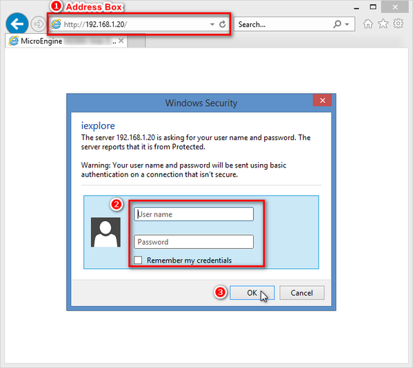
Step 1: Open IE browser (Internet Explorer) and type the default IP address in the address box.

Note

Default IP address for GT/GTR controllers: 192.168.1.20

.

.
Step 2: The Windows Security dialog box will be shown. Enter the User name and Password and click OK to continue.

Note

Default User Name: admin

Password: password10

.

.
The Windows Security Dialog Box
Figure 1: The Windows Security Dialog Box


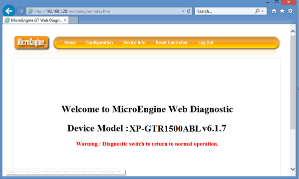
Step 3: Once the login is successful, the following home window will be shown:
The Web Diagnostic Home Window
Figure 2: The Web Diagnostic Home Window


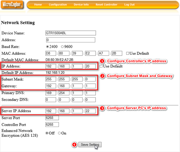
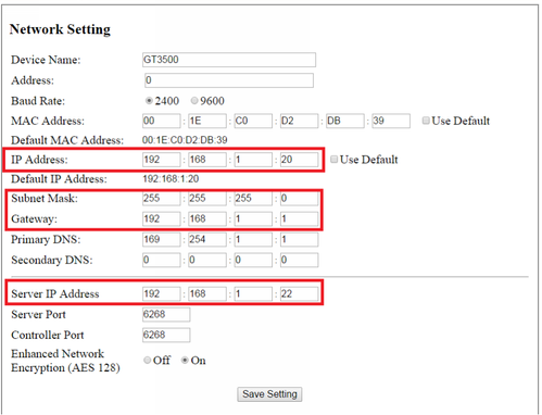
Step 3: Go to Configuration > Network. The Network Setting window will be shown. Configure the Controller's IP address, Subnet Mask, Gateway and Server PC's IP address settings. Click Save Setting to save the changes made.
The Network Setting Window
Figure 3: The Network Setting Window

.

Note

  • Once the settings are saved, the Web Diagnostic is only accessible via the newly changed controller IP address.
  • The controller and Server PC's IP addresses are required to be configured with static IP addresses.
  • The communication port between Server and controller is of ÚDP type with default port number: 6268.
  • Ensure Server and controller's IP addresses are unique IP addresses in the network and that both IP addresses are not already occupied by another device / controller.
  • Ensure that the setting for Enhanced Network Encryption (AES 128) is configured to be the same as the controller setting in the xPortalNet software. If the setting on Web Diagnostic does not match with the setting in the software, the controller will also be shown as "Down"

.

.

  • Method 2: To configure GT/GTR controller's IP address using on-board keypad programming:

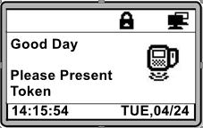
Step 1: The following home screen will be shown at the controller's LCD:
Controller LCD Home Screen
Figure 4: Controller LCD Home Screen

.
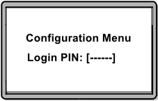
Step 2: To enter Configuration Menu for the first time, press asterisk key (*) and enter the 6-digits default MasterPIN.

Note

Default MasterPIN: 123456

.

.
Entering default MasterPIN for first time login
Figure 5: Entering default MasterPIN for first time login


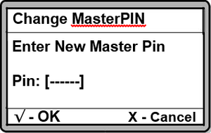
Step 3: The following window will then be shown to prompt users to enter a new MasterPIN which will be used for subsequent logins to enter Configuration Menu.
The Change MasterPIN Window
Figure 6: The Change MasterPIN Window


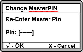
Step 4: Re-enter the same Master Pin and press to confirm the new 6-digits MasterPIN.
Re-enter the Same MasterPIN to Confirm the MasterPIN
Figure 7: Re-enter the Same MasterPIN to confirm the MasterPIN


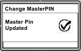
Step 5: The following window will be shown once the new MasterPIN is updated successfully.
The MasterPIN Updated Window
Figure 8: The MasterPIN Updated Window


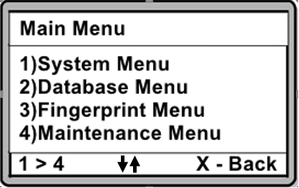
Step 6: Press the asterisk (*) key, followed by the new MasterPIN to enter Configuration Menu. The following Main Menu window will be shown upon entering Configuration Menu.
The Main Menu Window
Figure 9: The Main Menu Window


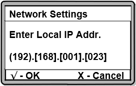
Step 7: Press 1 for System Menu. Press 7 to access the Network Settings menu. The following window will be shown. Enter the Local IP Address for the controller and press to proceed to the next window.
Enter the Local IP Address
Figure 10: Enter the Local IP Address


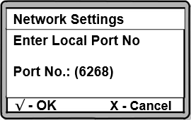
Step 8: At the following window, enter the Local Port No for the controller and press to proceed to the next window.
Enter the Local Port No
Figure 11: Enter the Local Port No

.

Warning!

The Port No. setting here MUST be the same as the setting for the software. Users are advised to use the default port no.

.

.
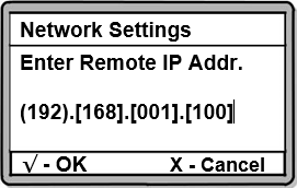
Step 9: Next, enter the Remote IP Address for Server's PC and press to proceed to the next window.
Enter the Remote IP Address (Server PC)
Figure 12: Enter the Remote IP Address (Server PC)


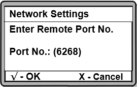
Step 10: The following window will be shown. Enter the Remote Port No. for the Server PC and then, press to proceed to the next window.
Enter the Remote Port No (Server PC)
Figure 13: Enter the Remote Port No (Server PC)

.

Warning!

The Port No. setting here MUST be the same as the setting for the software. Users are advised to use the default port no.

.

.
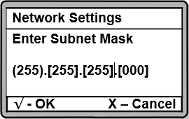
Step 11: At the following window, enter the Subnet Mask for the network and press to proceed to the next window.
Enter the Subnet Mask
Figure 14: Enter the Subnet Mask


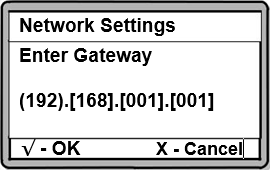
Step 12: Enter the Gateway IP for the network at the following window and press to proceed to the next window.
Enter the Gateway Setting
Figure 15: Enter the Gateway Setting


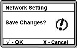
Step 13: Once users have completed all the settings, the following window will be shown to prompt users to save all changes Press to save all configuration settings. The controller will then auto restart to allow the changes to take effect immediately.
The Save Changes Window
Figure 16: The Save Changes? Window

.

Note

If users leave the process at any stage, all changes made previously will not be saved and will be lost. To save the network changes, press √ until users reach this window and press √ again to confirm saving the changes.

.

.

  • Method 3: To configure the GT/GTR controller's IP address using Device Lookup feature (xPortal3000):

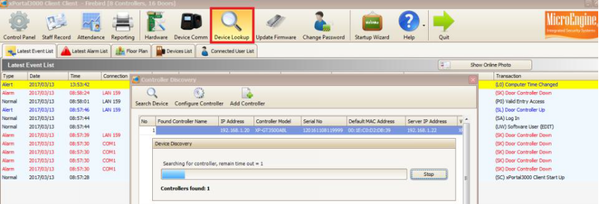
Step 1: Login to xPortal3000 Client software and click Device Lookup.
The Device Lookup Icon
Figure 17: The Device Lookup Icon


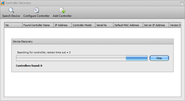
Step 2: The Device Discovery window will start searching for connected controller from the network.
The Device Discovery Window Searching for Controllers
Figure 18: The Device Discovery Window Searching for Controllers


Step 3: Select the detected controller and then click Configure Controller to change the controller settings.
Configuring the Detected Controller
Figure 19: Configuring the Detected Controller


Step 4: The following window will then be shown. Assign a new IP address, Subnet Mask, Gateway and Server IP address. Click OK to confirm and save the changes.
The Network Setting Window
Figure 20: The Network Setting Window

.

Note

  • The controller and Server PC's IP addresses are required to be configured with static IP addresses.
  • The communication port between Server and controller is of ÚDP type with default port number: 6268.
  • Ensure Server and controller's IP addresses are unique IP addresses in the network and that both IP addresses are not already occupied by another device / controller.
  • Ensure that the setting for Enhanced Network Encryption (AES 128) is configured to be the same as the controller setting in the xPortalNet software. If the setting on Web Diagnostic does not match with the setting in the software, the controller will also be shown as "Down"

.

.
Step 5: The window will prompt users to enter the user name and password. Enter the web diagnostic user name and password to proceed. 

Common Issues:

Often times after re-connecting to the network, the controller status may be shown as "Down" due to the controller and Server PC's IP addresses are automatically assigned as dynamic IP addresses (DHCP) in the network.

With dynamic IP address, a device can have different IP address every time it re-connects to the network or when the network detects that the IP address is already occupied by another device / computer.

So if the user found that the controller status is shown as "Down"; or the status is shown as "Up" and "Down" intermittently, check and ensure that both controller and Server PC's IP addresses are configured as static IP addresses.

Date Documentation:

24/4/2018 (Rev 1.0)

PROOF-READ

.

.


.

© MicroEngine Technology Sdn Bhd (535550-U). All rights reserved.