How to Troubleshoot RS-485 Communication Issue

Problem (Issue) Statement:

How to Troubleshoot RS-485 Communication Issue

Description:

A majority of MicroEngine's controllers and IO extension boards support RS-485 communication.

The RS-485 communication is a rugged, multi-drop serial data path that allows multiple devices to be connected with individual addresses for each device.

During installation, users will be following the general guide for RS-485 communication to install and terminate the hardware.

However, the RS-485 communication system might still present some issues. After observing most of the issues reported at site, the common cause of the issues are software setting errors, hardware configuration setting errors, loose wiring termination and even reversed cable polarity termination which affects the RS-485 communication reliability.

Related Software:

  • xPortalNet v1.5
  • xPortalNet PS v1.5
  • xPortalNet Lite v1.5
  • xPortalNet HS v1.5/ v1.8
  • xPortal3000

Related Hardware:

  • XP-M1000x
  • XP-M1000v2/ XP-M1300i
  • XP-M2000i/ XP-M2300
  • XP-GTR1200/ XP-GTR1500
  • XP-GT3200/ XP-GT3500
  • XP-SNET controller
  • XP-SNET-E32R/ XP-SNET- E248
  • XP-MK800E

System Application:

NIL

Symptom and Finding:

NIL

Cause:

NIL

Solution:

Summary:

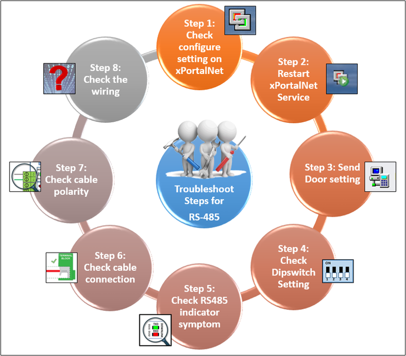
  • A quick guide to troubleshoot RS-485 issues.

Summary of Troubleshooting Steps
Figure 1: Summary of Troubleshooting Steps


Step-by-step Guide:

  • A quick guide to troubleshoot RS-485 issues:

Step 1: To check the configuration settings on xPortalNet software and ensure that all configuration settings are correct.


Step 2: Restart the xPortalNet Services or xPortal3000 Services.


Step 3: Go to xPortalNet Client > Device Comm > Send Door Setting or go to xPortal3000 Client > Device Comm > Send Door Setting.


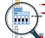
Step 4: Check DIP switch settings for Address Unit / Baud Rate on the controller board to ensure that the hardware configuration settings match with those in the software.

Figure 2: Ensure that Hardware Configuration Settings Match with Software Settings for Address Unit / Baud Rate


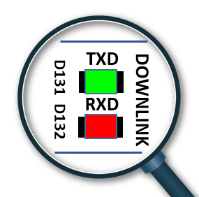
Step 5: To observe the communication pattern using RX and TX Led indicator which can help identify loose wiring termination or reversed polarity termination.
Observing RX and TX LED Indicators to Determine if Communication is Established
Figure 3: Observing RX and TX LED Indicators to Determine if Communication is Established


tikb-000275


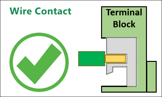
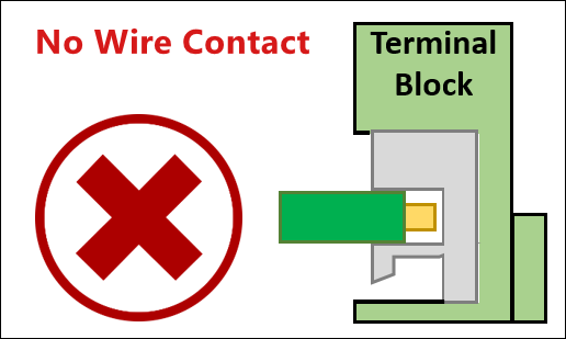
Step 6: Check the wiring connection. A very common wiring mistake that is easily overlooked is the possibility of loose or obstructed wires.
Side View Illustration of Correct Wiring Termination at Terminal Block
Figure 4: Side View Illustration of Correct Wiring Termination at Terminal Block


Side View Illustration of Incorrect Wiring Termination which may Affect System Communication
Figure 5: Side View Illustration of Incorrect Wiring Termination which may Affect System Communication


This step is important to double and even triple check the wiring installations because even if a wire looks like it is properly connected, it may not necessarily be so.


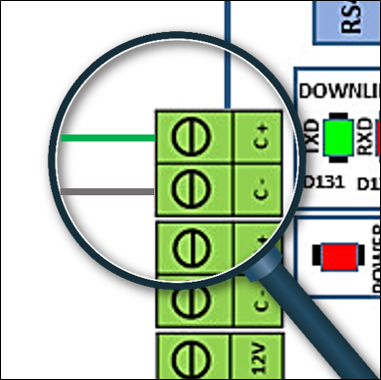
Step 7: Check wiring termination polarity. Even the most skilled technicians can sometimes make a simple wiring mistake. Refer to the label shown on the controller board or IO board and be certain that you have terminated the wiring according to the correct polarity.
Check and Ensure that the Wiring Termination Polarity is Correct
Figure 6: Check and Ensure that the Wiring Termination Polarity is Correct


Step 8: If nothing worked to solve the problem, users can refer to the wiring guideline for RS-485 to proceed with the second troubleshooting guideline.

Knowledge Base Link

User may refer TIKBxxx- A Wiring Guidelines for RS-485 network to solve the RS485 issue/ problem.

Common Issue

NIL

Date Documentation:

12/11/2018 (Rev 2.0)

PROOF-READ

.

.


.

© MicroEngine Technology Sdn Bhd (535550-U). All rights reserved.