Summary:
Step-by-step Guide:
Step 1: To avoid signal reflections which can cause communication errors, the Daisy Chain topology is highly recommended. The Daisy Chain topology is designed as one continuous line with multiple drops instead of similar to a star.

Figure 1: Daisy Chain Topology in Detail
Step 2: The picture below shows several typical wiring configurations observed from site, with Daisy Chain's topology being the only acceptable configuration.

Figure 2: Frequently Observed Wiring Connection, with Daisy Chain being the Only Acceptable Configuration
Step 1: RS-485 standards allow communications of up to a maximum of 1km cable length for a network segment. This length is the total cable length between the first controller in the network and the last controller in the network. It is not the length between one controller to the next successive controller. Refer to the following picture for further information

Figure 3: 1km Maximum Cable Length Requirement Between First and Last Controller in the Network
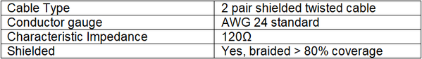
Step 1: RS-485 specification recommends shielded twisted pair cable to reduce two major sources of problems for external noise: radiated EMI and received EMI.
Step 2: The recommended cable specifications are as follows:
Example of the shielded twisted pair cable:

Figure 4: Shielded Twisted Pair Cable Illustration