I have just Installed a XP-GT3200 or XP-GTR1200 Controller but it is Not Responding to Flashed Valid Access Card
| Problem (Issue) Statement: | I have just installed a XP-GT3200 or XP-GTR1200 Controller but it is not responding to flashed valid access card |
| Description: | After installing a XP-GT3200 / XP-GTR1200 unit, the door lock is not responding to the flashed valid access cards. |
| Related Software: | NIL |
| Related Hardware: |
|
| System Application: | Door Controller Mode |
| Symptom and Finding: | Downlink icon is not indicated on the controller's screen Door lock does not release / respond after flashing a valid access card. |
| Cause: |
|
| Solution: | Summary:. Step-by-step Guide:
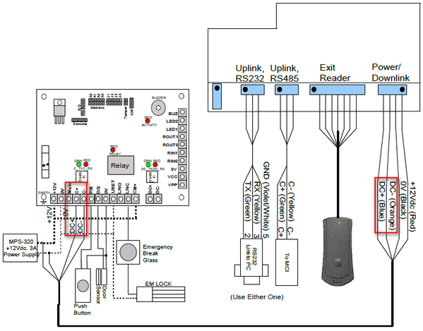
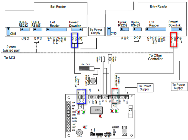
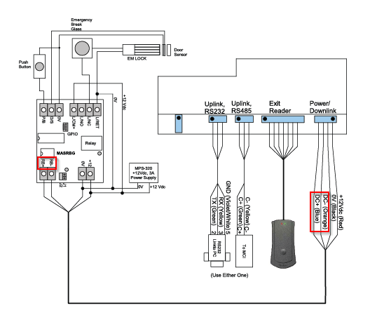
Step 1: Check and ensure that the wiring connection is correct .
.
. .
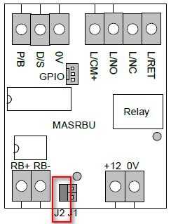
Step 1: Check and ensure that Jumper J2 on MAS-RBU is shorted while MAS-RBT is opened. . .
Step 1: Connect site's current relay board to other known functional controller. Refer to Check Wiring Connection above for the relevant wiring diagram connection diagrams. Troubleshooting Explanation
. . Step 2: Connect other known functional relay board to the current controller. Refer to Check Wiring Connection above for the relevant wiring diagram connection diagrams. Troubleshooting Explanation
|
| Common Issues: | NIL |
| Porting Date: | 26/11/2018 (Rev 1.0) |
PROOF-READ
.
.
.
© MicroEngine Technology Sdn Bhd (535550-U). All rights reserved.


