How to Configure and Setup XP-SNET-GAC

Problem (Issue) Statement:

How to configure and setup XP-SNET-GAC?

Description:

A guide to configure and setup XP-SNET-GAC.

The XP-SNET-GAC controller supports Global AntiPassBack by cluster. The GAC controller acts as a centralized look up device with immediate location information update. Controllers at other doors will immediately obtain the latest location information of the card user.


Note

XP-SNET-GAC controller is only supported for LAN Network Communications only.

.

Tip

Controller models supported as GAC Client: XP-SNETv3.36, XP-SNETv4, XP-M2000i v6.10 and above, and XP-M1000i v6.00 and above.

Related Software:

  • xPortalNet v1.5

Related Hardware:

  • XP-SNET-GAC v2.24

System Application:

  • High Level Lift Integration

Symptom and Finding:

NIL

Cause:

NIL

Solution:

Warning!

XP-SNET-GAC currently do not support odd numbered card lengths, e.g. 5, 7, 9 card number lengths.

Summary:


Step-by-step Guide:

  • To perform ColdStart after first power up:

Step 1: Press & hold COLDSTART button on XP-SNET-GAC board.

.
Step 2: Press & release RESET button on XP-SNET-GAC board.

.
Step 3: Wait for STAT & CPU LED to light up simultaneously.

.
Step 4: Release COLDSTART button.

Users are advised to perform ColdStart operation once after every first time power up of the controller; or when advised to do so by the technical support.


  • To perform pre-configuration setting for the network connection:

Knowledge Base Link

Users may refer to How to Pre-configure Network Connection for IP Controllers to complete the process.


  • To perform network configuration settings for XP- SNET-GAC via Web Diagnostic: 

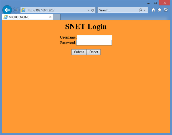
Step 1: Open IE browser (Internet Explorer) and type the XP-SNET-GAC IP address in the address box. (Default IP address: 192.168.1.220)


Step 2: Enter the Username and Password and click Submit to login.
SNET Login Window
Figure 1: SNET Login Window


Step 2: The Welcome page will be shown as below. Click on Network Setting tab to continue.
Web Diagnostic Welcome Page
Figure 2: Web Diagnostic Welcome Page


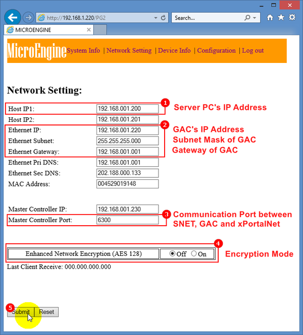
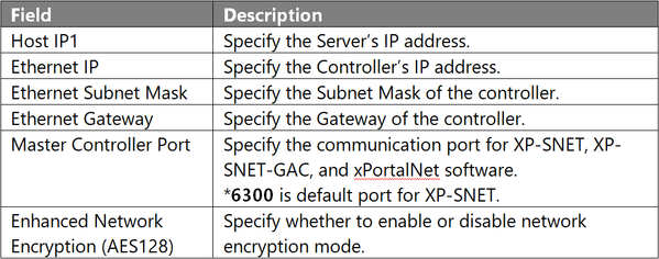
Step 3: The Network Setting page will be shown. Configure the network setting according to the table that follows. Click Submit to save the changes made.
Network Setting Page
Figure 3: Network Setting Page


Step 3: Click Log out to exit from web diagnostics.
Logging Out from Web Diagnostic
Figure 4: Logging Out from Web Diagnostic

Common Issue

NIL

Date Documentation:

2/11/2018 (Rev 1.0)

PROOF-READ

.

.


.

© MicroEngine Technology Sdn Bhd (535550-U). All rights reserved.