How to Setup Connection, Controller, and Door Settings using xPortal3000 Startup Wizard
| Problem (Issue) Statement: | How to setup Connection, Controller, and Door settings using xPortal3000 Startup Wizard |
| Description: | This article will guide users to setup Connection, Controller, and Door settings using xPortal3000's built-in Startup Wizard. |
| Related Software: |
|
| Related Hardware: | NIL |
| System Application: | NIL |
| Symptom and Finding: | NIL |
| Cause: | For first time guide on how to setup Connection, Controller, and Door settings using xPortal3000's built-in Startup Wizard. |
Warning!
. . Summary:
. Step-by-step Guide:
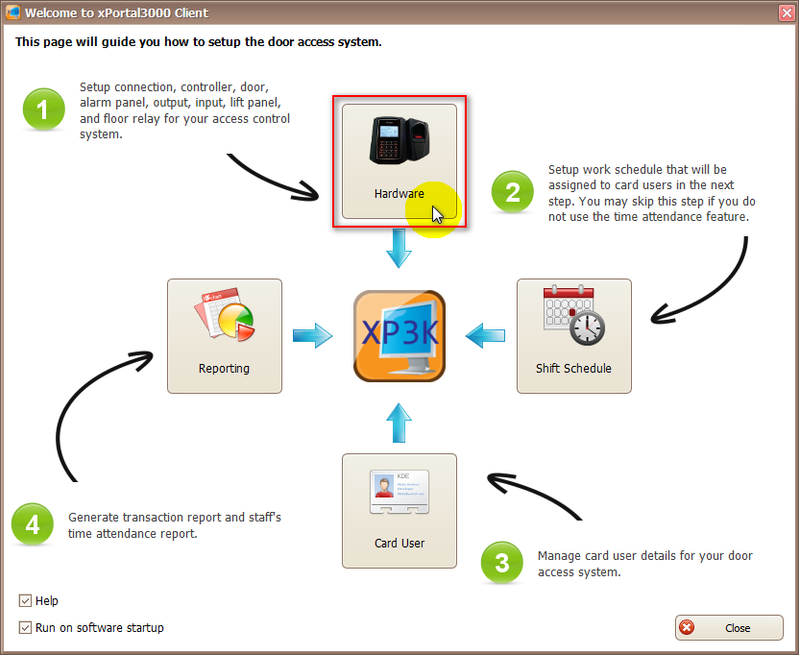
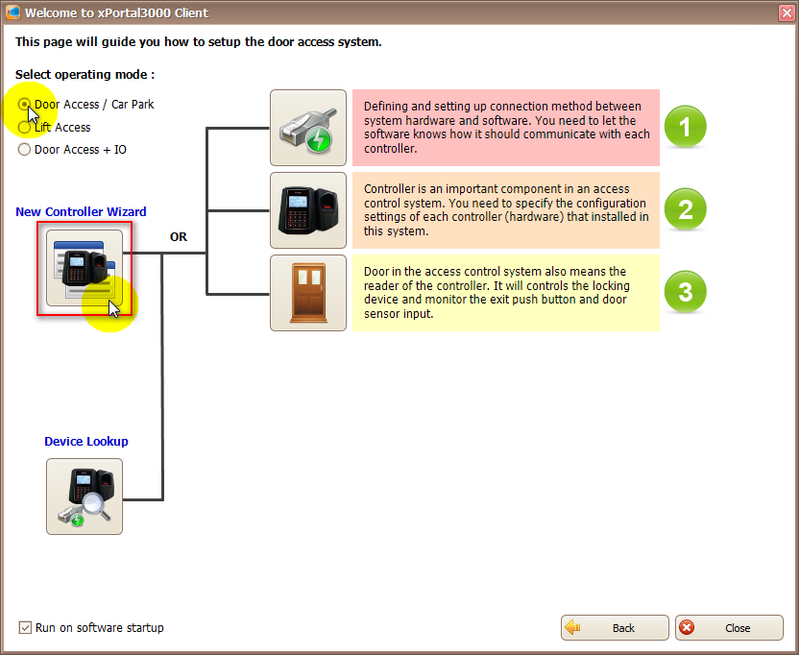
Step 1: Login to xPortal3000 Client. Click Startup Wizard icon. The Startup Wizard window will be shown. Click on Hardware icon. . Step 2: The following window will then be shown. Select the corresponding operating mode of the controller, and click New Controller Wizard icon. . .
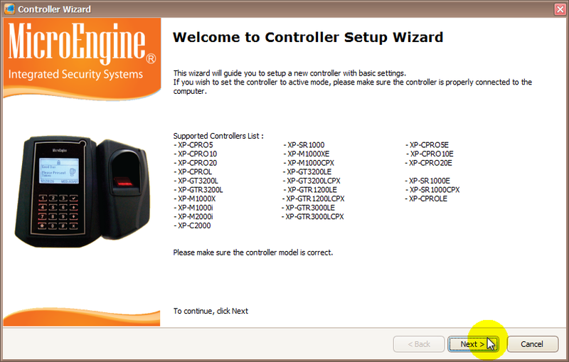
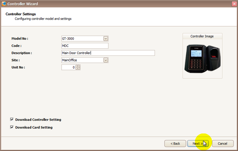
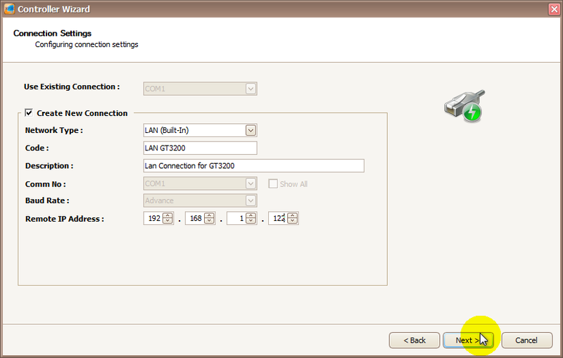
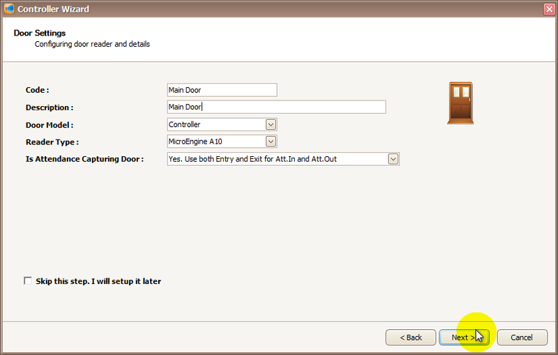
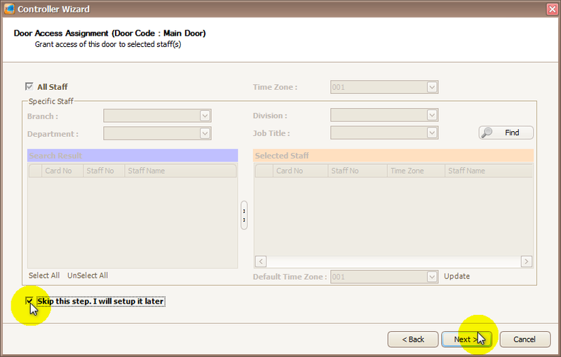
Step 1: The Controller Wizard window will then be shown after users click on New Controller Wizard icon. This window displayed all the controllers supported in the xPortal3000 software. If the controller model is not listed in this list, this means that the controller is not supported for the respective software version. Click Next to continue. . Step 2: The Controller Settings window will then be shown. Enter the information of the controller accordingly and click Next to continue. . Step 3: Next, the Connection Settings window will be shown. Enter the information of the connection accordingly and click Next to continue. . Note Note that the screenshot shows the settings for a connection using LAN connectivity. . . Step 4: The Door Settings window will then be shown. Enter the information of the door accordingly and click Next to continue. . Step 5: The Door Access Assignment window will then be shown. If users are configuring door access for the first time and there are no Staff Records or Time Zones configured yet, users can choose to skip this step by ticking the Skip this step. I will setup it later checkbox. Click Next to continue. . .
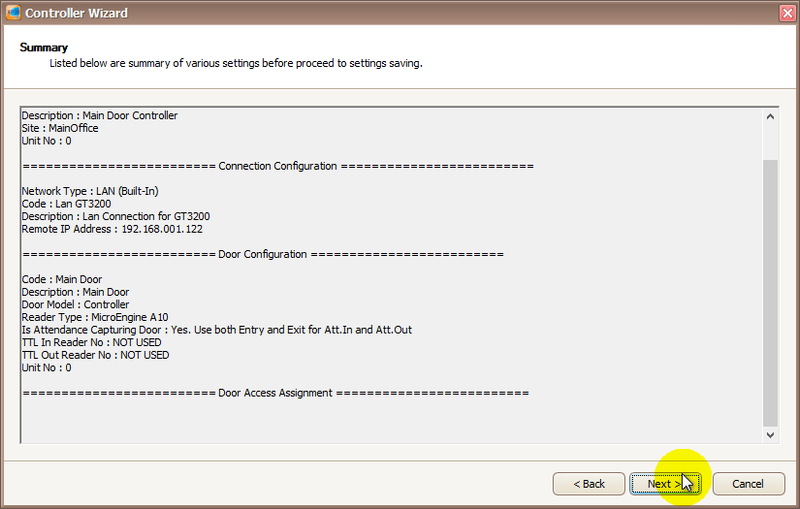
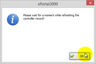
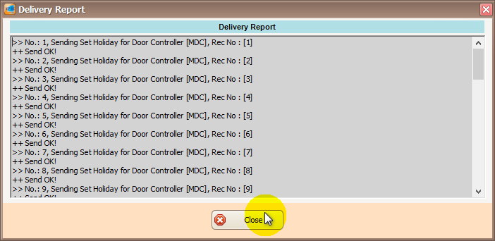
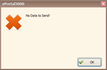
Step 1: Once users have configured the Controller, Connection, and Door settings, the Summary window will be shown. Click Next to continue. . Step 2: The software will then prompt the following message to allow the software to refresh the controller records to reflect the new changes. Click OK to continue. . Step 3: In the Delivery Report window shown next, make sure that all the sending of data to the controller is OK. Click Close to exit from the window. . Step 4: The software will then prompt 2 similar windows. Users can ignore this message and click OK to continue. . .
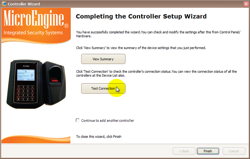
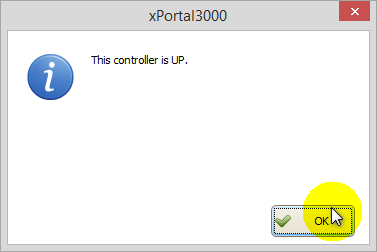
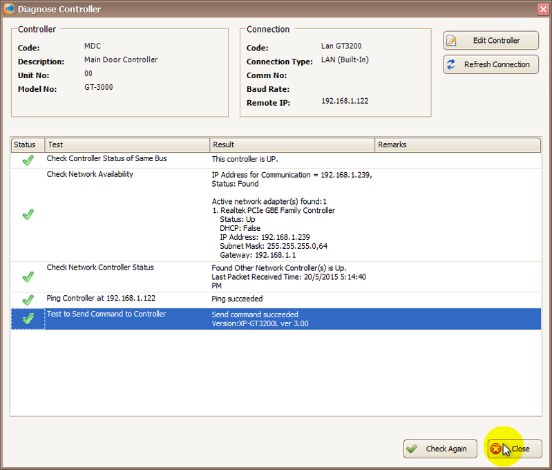
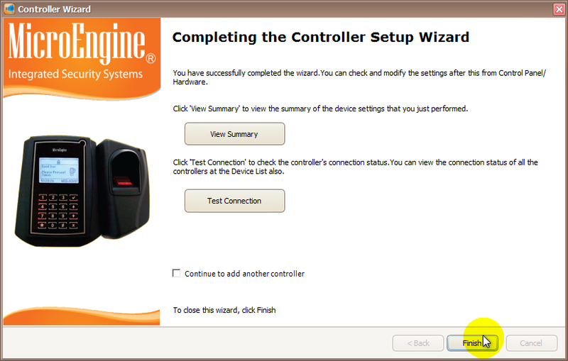
Step 1: After the No Data to Send window, the Completing the Controller Setup Wizard window will be shown. Users can click on Test Connection to test the configured connection point. . Step 2: Ensure that the following window is shown to indicate that the controller's status is Up. . Step 3: At the Diagnose Controller window, ensure that the status of all the tests are passed with a green tick. Click Close to continue. . Step 4: Back at the Completing the Controller Setup Wizard window, click Finish to exit from the window. . Step 5: At the Device List window, the controller and door should have the statuses as Up respectively. .
| |
| Common Issues: | NIL |
| Porting Date: | 8/4/2019 |
PROOF-READ
.
.
.
© MicroEngine Technology Sdn Bhd (535550-U). All rights reserved.
