How to Configure Connection, Controller, and Door Settings for XP-GLS5000 Controller with xPortalNet HS v1.8 Software
Problem (Issue) Statement: | How to configure connection, controller, and door settings for XP-GLS5000 controller with xPortalNet HS v1.8 Software? |
Description: | How to configure connection, controller, and door settings for XP-GLS 5000 controller with xPortalNet HS v1.8 software? |
Related Software: |
|
Related Hardware: |
|
System Application: |
|
Symptom and Finding: | NA |
Cause: | How to configure connection, controller, and door settings for XP-GLS 5000 controller with xPortalNet HS v1.8 software? |
Solution: | Warning!
. . Summary:Tips Please configure the IP address for XP-GLS5000 controller before configuring connection, controller, and door settings. Users may refer to How to Configure IP Address for IP Controllers for the complete pre-configuration steps. Step-by-step Guide:
Step 1: Launch the xPortalNet HS Comm Service.
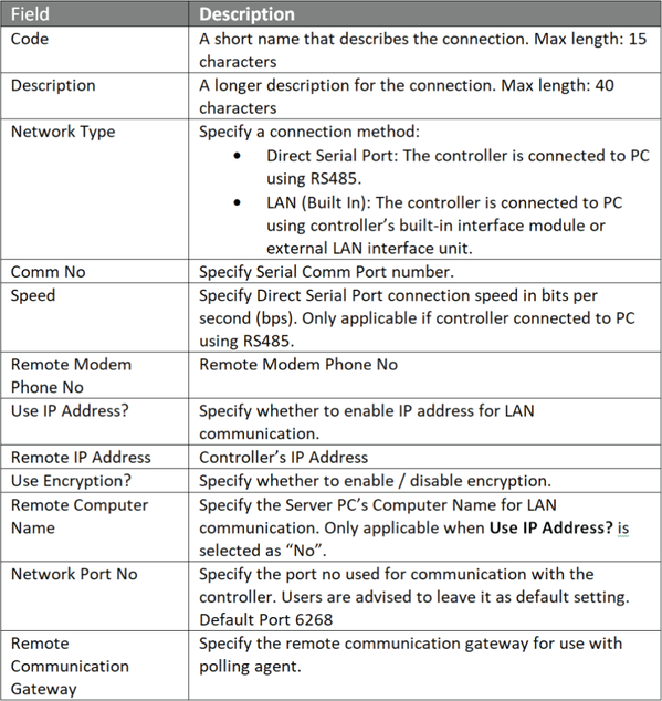
Step 1: Go to xPortalNet HS Server > Server Admin > Connection Setup. The Connection Setup window will be shown as below. Click Add to add a new connection.
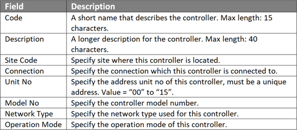
Step 1: Go to Server Admin > System Device Setup > Controller. The Controller Setup window will be shown as below. Click Add to add a new controller.
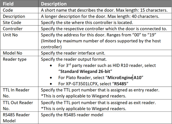
Step 1: Go to Server Admin > System Device Setup > Door. The Door Setup window will be shown as below. Click Add to add a new controller.
|
| Common Issues | Nil |
Date Documentation: | 13/2/2019 |


PROOF-READ
.
.
.
© MicroEngine Technology Sdn Bhd (535550-U). All rights reserved.