Step 1: The XP-SNET-E32R address setting for the DIP switch can be referred to as shown below:
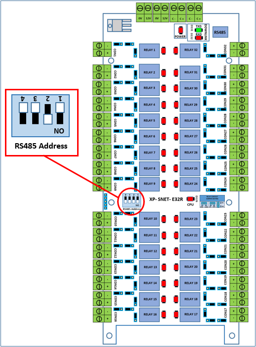
Figure 1: The DIP switches for address setting location on the XP-SNET-E32R extension board
Step 2: The table below shows the different DIP switch configurations for the respective address settings:

Step 3: The table below shows an example of the DIP switches settings for a XP-SNET-E32R extension board to be configured with address setting of unit no. "01":

Step 1: On the XP-SNET controller, ensure that both D33 & D34 LEDs in the "Downlink" section (lower left section of XP-SNET controller) is blinking to indicate that the XP-SNET controller has successfully established communication with the XP-SNET-E32R extension board.
Step 2: On the XP-SNET-E32R extension board, ensure that both Uplink LEDs are blinking. All output relay LEDs on the XP-SNET-E32R extension board will then be turned ON.