I have Just Installed a New XP-GT or XP-GTR Controller but it's Status is Shown as Down in Device List
| Problem (Issue) Statement: | I have just installed a new XP-GT or XP-GTR controller but it's status is shown as Down in Device List |
| Description: | After installing the new XP-GT or XP-GTR controller, the controller status in Device List is shown as "Down". The controller failed to establish communication with the software. |
| Related Software: | NIL |
| Related Hardware: |
|
| System Application: | Door Controller Mode |
| Symptom and Finding: |
|
| Cause: | There are several potential causes which contributes to the same symptoms: Connection Settings:
Network Settings:
|
| Solution: | Information This article serves as a starting platform for users to begin troubleshooting controller status "down" issues Summary:
. Step-by-step Guide:
Step 1: Check the Uplink Communication icon on the LCD of the controller. If the icon is present and not blinking, this indicates that the controller is able to establish communications with the software. Step 2: If the Uplink Communication icon is absent, then it means that the controller failed to communicate with the software, users should then proceed with the remainder of this article.
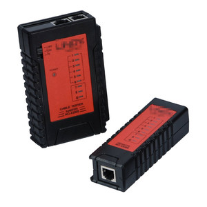
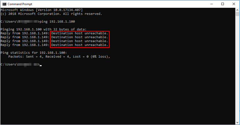
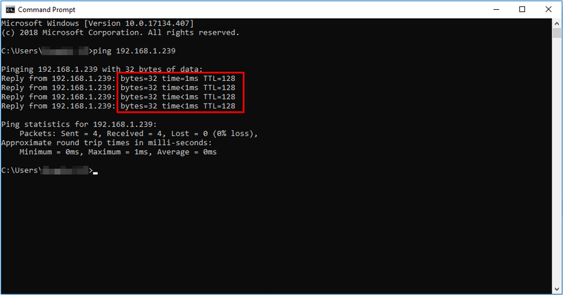
Step 1: Check and ensure that the controller is connected to a network switch / router, and that the network switch / router is powered on and in running condition. Step 2: Check and ensure that the network cable used is in good, working condition. Users are advised to test the connectivity of the cable by using a network cable tester. Step 3: Before assigning any IP Address, users should ensure that the IP Address does not conflict with other devices. To do that, users must try to ping the IP Address before hand via Windows Command Prompt.
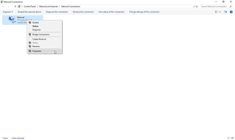
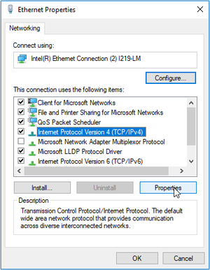
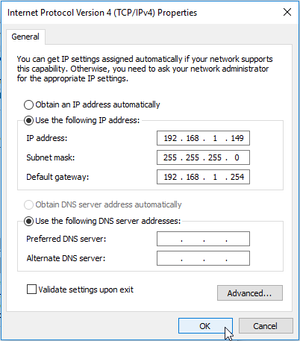
Step 4: To check whether the Server PC's IP Address is static or dynamic, 1. Go to Network Connections window, right-click on the Ethernet and select Properties. 2. The Ethernet Properties window will then be shown. Select Internet Protocol Version 4 (TCP/IPv4) and click Properties. 3. The Internet Protocol Version 4 (TCP/IPv4) Properties window will be shown. Ensure that the Use the following IP address checkbox is ticked, enter IP address of the Server PC and click OK. Step 5: Users should also check and ensure that the Network Parameters configured on the controller LCD screen matches with the configuration in the software.
Step 1: Users must allow the application (xPortal software) to communicate through the Windows Firewall. Knowledge Base Link Users can refer to How to Allow Software to Communicate Through Windows Firewall for the complete steps to allow the application to communicate through the Windows Firewall. |
| Common Issues: | NIL |
| Porting Date: | 29/11/2018 (Rev 1.0) |
PROOF-READ
.
.
.
© MicroEngine Technology Sdn Bhd (535550-U). All rights reserved.
