.
.
.
Step 1: Refer to wiring diagram as shown below for wet contract output with NC (Normally Closed) contact type.
 with Normally Closed Contact Type")
Figure 1: Wiring Diagram for Wet Contact Output (Electromagnetic Lock) with Normally Closed Contact Type
Or
 with Normally Closed Contact Type")
Figure 2: Wiring Diagram for Wet Contact Output (Drop Bolt Lock) with Normally Closed Contact Type
Step 2: Refer to wiring diagram as shown below for wet contact output with NO (Normally Opened) contact type.
 with Normally Opened Contact Type")
Figure 3: Wiring Diagram for Wet Contact Output (Strobe Light with Siren) with Normally Opened Contact Type
Step 3: Refer to wiring diagram as shown below for dry contact output with NC (Normally Closed) contact type.
 with Normally Closed Contact Type")
Figure 4: Wiring Diagram for Dry Contact Output (Integration with PA System) with Normally Closed Contact Type
Step 4: Refer to wiring diagram as shown below for dry contact output with NO (Normally Opened) contact type.
 with Normally Opened Contact Type")
Figure 5: Wiring Diagram for Dry Contact Output (Traffic Barrier Gate) with Normally Opened Contact Type
.
.
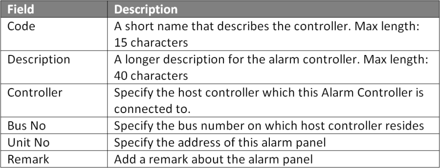
Step 1: Go to Server Admin > System Device Setup > Alarm Controller > Add. The Add Alarm Controller window will be shown as below:

Figure 6: Alarm Controller Window
.
.
Step 2: The following message window will be prompted to show Record is Added. Click OK to continue.

Figure 7: Record Added Window
.
.
Step 1: Go to Server Admin > System Device Setup > Output Point. The Output Setup window will be shown as below.

Figure 8: Output Setup Window
Step 2: Click Add to add a new output setup. The Add Output window will be shown as below.

Figure 9: Add Output Window
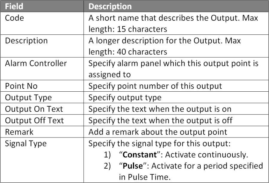
Step 3: Fill in the respective fields and click OK to save the changes.

Figure 10: Output Table Fields
.
.
Step 4: The following message window will be prompted to show that Record is Added. Click OK to continue.
Figure 11: Record Added Window
Step 5: Users can proceed to configure built- in input points on the controller and create an Instruction Control configuration to specify the relationship between the Input & Output points.