| Problem (Issue) Statement: | How to connect XP-SK32 Controller to door accessories |
| Description: | XP-SK32 is MicroEngine's legacy standalone controller. This article will guide users on how to connect the standalone controller to the door accessories. |
| Related Software: | NIL |
| Related Hardware: |
|
| System Application: | NIL |
| Symptom and Finding: | NIL |
| Cause: | For first time guide on how to connect XP-SK32 to the door accessories. |
| Solution: | Summary:
. Step-by-step Guide:
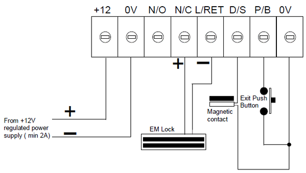
Step 1: Please refer to the following wiring diagram for the connections between the XP-SK32 controller to the door accessories: . Step 2: Power ON the reader by connecting it to a power supply with 12VDC and 3A current rating. Ensure that when the door security status is ON, the EM lock is in locked condition and vice versa. . Step 3: Ensure that when users pressed the exit button, the EM lock is released and the LED on MAS-RB is turned on when the EM lock is released. |
| Common Issues: | NIL |
| Porting Date: | 27/3/2019 |
PROOF-READ
.
