Problem (Issue) Statement: | How to troubleshoot the issue where controller status is shown as Down in xPortal software while the LED indicators of the controller are blinking abnormally or remained lighted up. |
Description: | A guide to troubleshoot the controller status being down when the LED indicators of the controller are blinking abnormally or remained lighted up. |
Related Software: |
|
Related Hardware: |
|
System Application: |
|
Symptom and Finding: | Customer complained that the controller status is shown as Down in the respective xPortal software. Technical support attending to the site is also unable to ping the IP address of the IP controller through Command Prompt. When the technical support looked at the controller, it is discovered that the LED indicators of the controller are blinking abnormally or remained lighted up. |
Cause: |
|
Solution: | Summary:
. Step-by-step Guide:Tips Users are required to prepare a digital multi-meter and a network tester kit to troubleshoot for this issue.
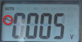
Step 1: Press SELECT button to change the voltage measuring mode to DC (Direct Current) voltage. . Tips The display screen will show the following symbol when the digital multi-meter is in DC voltage mode. . . Step 2: Touch the BLACK probe to the COM terminal and the RED probe to the V terminal on the switching power supply to measure the power supply output voltage . Step 3: User will be able to read the voltage values displayed on screen. Practically the voltage values should be ±10% of 12VDC. Different switching power supply may deliver different DC output. User may check on the specification of the switching power supply for reference. . Step 4: Touch the BLACK probe to the 0V terminal and touch the RED probe to the 12V terminal on the incoming power connectors for the controller as shown below using the XP-M2000i as an example. User will be able to read the voltage values displayed on screen which practically should be ±10% of 12VDC. . Step 5: If, read the voltage value less than 12Vdc from switching power supply unit, please replace a new switching power supply unit. Note As a safety precaution, user to confirm the incoming power supply is within ±10% of 240VAC as unstable incoming power supply will also spoil the switching power supply. . .
Step 1: Press SELECT to change the voltage measuring mode to AC (Alternating Current). . Tips . Step 3: Touch the BLACK probe to the NEUTRAL terminal and touch the RED probe to the LIVE terminal on the switching mode power supply unit. . Step 4: Switch ON the power supply and you will be able to read the voltage values displayed on screen. If the incoming power supply 240VAC was tested ok, user may continue on to check the incoming power supply 12Vdc to controller. . Note Theoretically the tolerance level defined by IEC60947-2 is 0.85% for minimum nominal voltage (Un) and 1.1% for maximum nominal voltage (Un). |
Common Issue: | NIL |
Date Documentation: | 24/3/2020 (Rev 1.0) |


PROOF-READ
.
Related Articles.
Containing the label "hardware-configuration"
Filter by label
There are no items with the selected labels at this time.