Skip to end of metadata
Go to start of metadata

You are viewing an old version of this page. View the current version.

Compare with Current View Page History

« Previous Version 6 Next »

Problem (Issue) Statement:

How to configure input and output settings for XP-SNET-E248 extension board?

Description:

A guide to configure input and output settings for XP-SNET-E248 extension board.

Related Software:

NA

Related Hardware:

  • XP-SNET-E248

System Application:

  • Alarm Monitoring System

Symptom and Finding:

NA

Cause:

For first time configuration on input and output settings for E248 extension board.

Solution:


677px450


Summary

  • General Overview of the input and output points on the XP-SNET-E248 extension board.

  • To configure jumper settings for the output relay on XP-SNET-E248 extension board.

  • To connect external outputs to XP-SNET-E248 extension board.

  • To connect supervised inputs to XP-SNET-E248 extension board.

Step-by-step Guide:

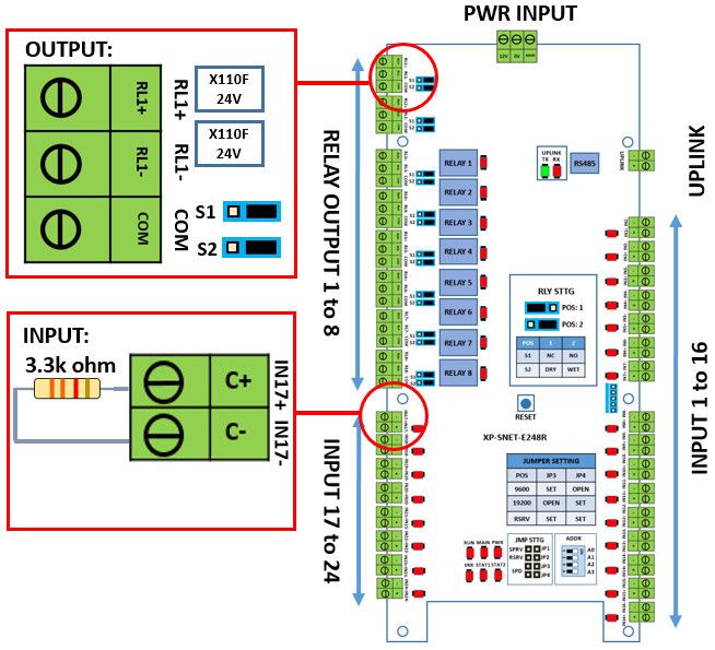
  • General Overview of the input and output points on the XP-SNET-E248 extension board:

Step 1: Please refer to the figure as shown below for an overview of the input and output points on the XP-SNET-E248 extension board:
 
Figure 1: Overview of input and output points on the XP-SNET-E248 extension board


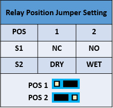
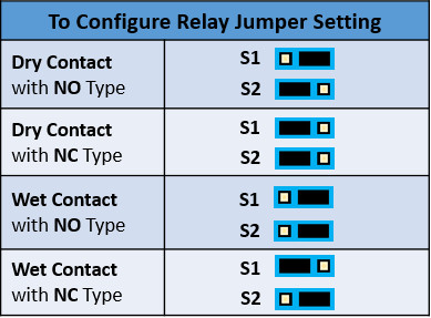
  • To configure jumper settings for the output relay on XP-SNET-E248 extension board:

Step 1: Follow the table below to configure the jumper settings according to the specification for the output relays (dry contact vs wet contact & NO contact vs NC contact).


Step 2: The table below shows the examples according to different combinations of output relay specifications:


Note

  • The black bar indicates the pins required to be shorted.
  • The default jumper setting on XP-SNET-E248 extension board is Wet Contact with NO type.


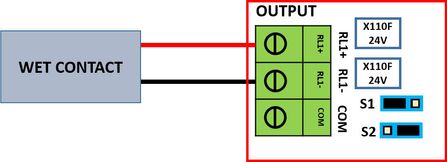
  • To connect external outputs to XP-SNET-E248 extension board:

Step 1: Please refer to the figure as shown below for Wet Contact relay output:  

Figure 2: Wet contact output connection


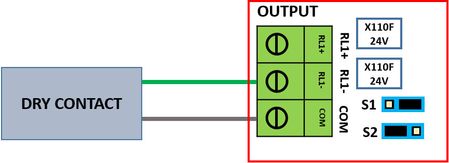
Step 2: Please refer to the figure as below for Dry Contact relay output.

Figure 3: Dry contact output connection


  • To connect supervised inputs to XP-SNET-E248 extension board:

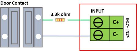
Step 1: Please refer to the figure as below for Normally Closed (NC) Sensor Input:
 
Figure 4: Normally closed (NC) sensor type input connection


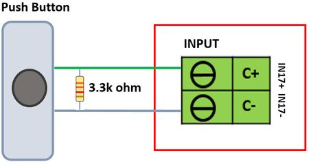
Step 2: Please refer to the figure as below for Normally Open (NO) Sensor Input
 
Figure 5: Normally open (NO) sensor type input connection


Note

For supervised inputs, the value of the resistor connected is 3.3kΩ

Date Documentation:

19/6/2018 (Rev 1.1)


  • No labels